
How to lay out a 90° fishmouth joint in metal fabrication
Learn the development and flat pattern development of a 90° branch connection between pipes of the same diameter.
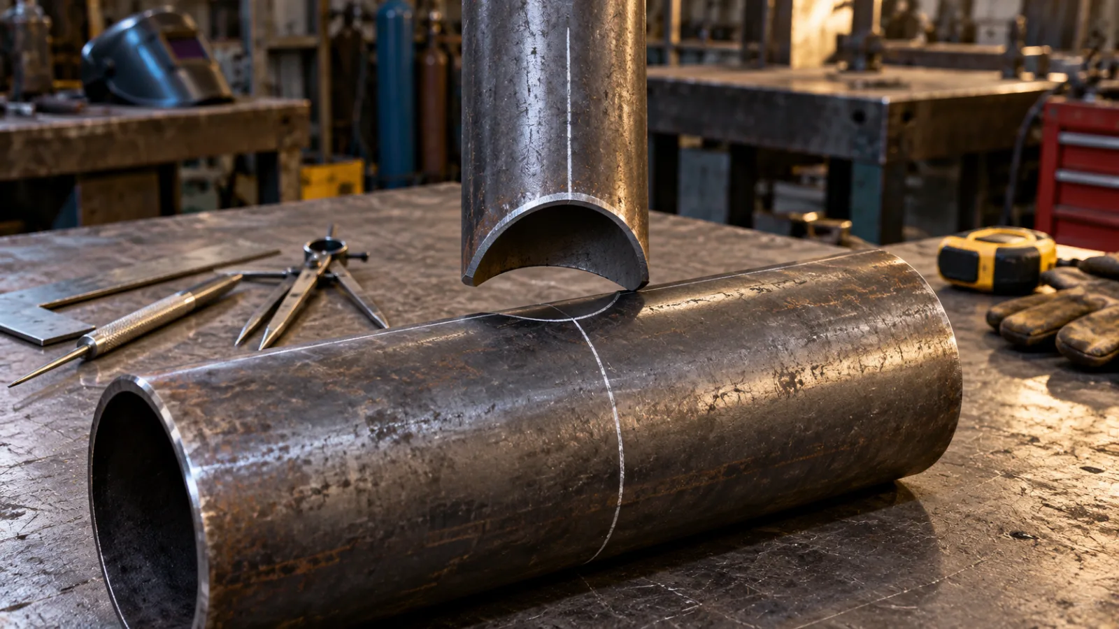
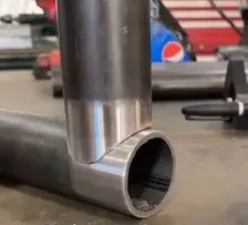
A fishmouth joint is a classic metal fabrication layout used when the end of one pipe needs to fit the curved surface of another pipe.
Instead of making a straight cut at the end of the pipe, a curved profile is created that follows the geometry of the pipe where the joint will be made.
In this article, we will specifically work with one situation:
two pipes of the same diameter;
centralized axes;
pipes meeting at 90°;
development of the pipe end that will be fitted.
This definition is important because a fishmouth with pipes of different diameters, offset axes, or angles other than 90° generates a different profile and requires a layout corresponding to the new geometry.
What is a fishmouth?
Imagine a horizontal pipe and another pipe approaching it perpendicularly.
If the end of the second pipe is simply straight, it will only touch the first pipe at a few points and leave large gaps on the sides.
For the two surfaces to meet properly, it is necessary to remove material from the end of the pipe that will be fitted.
The resulting shape has two more advanced regions and two more recessed regions, creating the profile known in piping and metal fabrication work as fishmouth.
Geometrically, we are dealing with the intersection between two cylindrical surfaces.
When pipes have the same diameter, their axes intersect, and the angle between them is exactly 90°, the design shows strong symmetry.
Which method is used to create this layout?
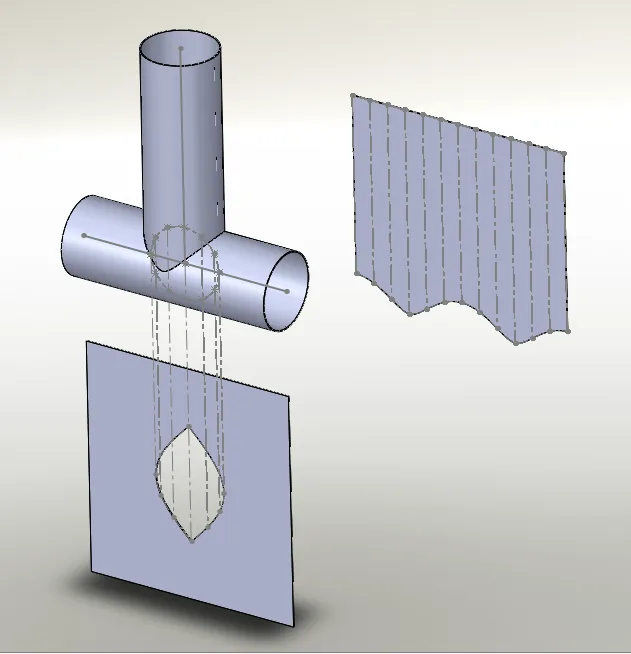
For this type of development, the parallel line method.
can be used. This method is suitable for the development of cylindrical surfaces because the generatrices of the cylinder remain parallel to each other.
The layout logic is:
represent the position of the two pipes;
divide the circumference of the pipe that will be cut;
project these divisions onto the intersection;
unroll the pipe's circumference into a straight line;
transfer each height to its corresponding position;
join the obtained points;
form the final contour of the coping.
The technique of dividing the profile, projecting its generatrices, and transferring the points to the development is the basis of this type of layout.
Required materials and instruments
To perform the layout manually, the following will typically be used:
ruler;
square;
compass;
pencil or scriber;
tape measure;
flexible ruler or French curve;
paper, cardboard or other material to make the template;
calculator.
If the drawing is being made directly on the plate, the actual manufacturing conditions of the part must also be considered.
Measurements you need to know
Before starting, correctly identify:
D — Pipe diameter
In the example of this article, both pipes have the same diameter.
E — Wall or plate thickness
It will be important especially when we are producing the cylinder from a plate.
L — Available branch length
It is the distance required to position the fishmouth layout relative to the other end of the part.
Intersection angle
In this case:
90°
Pay attention to the diameter used in the development
This is an important point because there are two different situations.
Case 1 — You are making a template for an existing pipe
If the goal is to produce a paper template to wrap around a finished pipe, the length of this template needs to follow the actual external circumference of the pipe.
In this case:
C = π × De
Where:
C = template length;
De = actual external diameter of the pipe;
π ≈ 3.1416.
This happens because the paper will be placed on the outer surface of the pipe.
Technical template generators for tube notching use precisely the outer diameter of the pipe to determine the extent that will be wrapped around it.
Case 2 — You are developing your own sheet metal part
When the cylinder will be produced from sheet metal and subsequently rolled, the neutral axis of the thickness must be considered.
In this case, the mean diameter.
is used.
If you have the outside diameter:
Dm = De − E
If you have the inside diameter:
Then:
C = π × Dm
This difference exists because the plate development should approximately follow the neutral axis of the material, and not simply the outer surface.
Therefore:
finished pipe + external template → use the outer diameter
cylinder fabrication from plate → consider the mean diameter
Do not mix the two cases.
Carry TraceClub in your pocket
Boilermaking layouts, calculations and technical manuals in the palm of your hand — fast, accurate and always with you in the shop or in the field.
- Available for iOS and Android
- Works offline
- PT · EN · ES
Step 1 — Draw the elevation view
Start by representing the two pipes.
Draw the main pipe horizontally.
Next, draw the pipe that will receive the fishmouth perpendicular to the first, forming exactly 90° between the axes.
Since we are working with pipes of the same diameter, both must have the same width in the representation.
Also lay out:
horizontal axis of the main pipe;
vertical axis of the branch;
region where the intersection will occur.
The intersection of the axes must be centered.
This will be the geometric base for the rest of the development.
Step 2 — Create the circular profile of the pipe
Now draw a circle corresponding to the diameter of the pipe that will receive the cut.
It is not always necessary to work with the full circumference.
Since there is symmetry, it is possible to construct the layout using a semi-circumference and then repeat the corresponding points.
For didactic purposes, we can divide the full circumference into 12 equal parts.
Consequently, the semi-circumference will have 6 divisions.
The method with 12 divisions is widely used because it offers a good number of points and allows the circle to be constructed relatively simply. The technical development of a 90° tee of the same diameter can also be executed by dividing the profile into six parts and the complete development into twelve.
Step 3 — Number the points
After dividing the profile, number all the points.
For example:
1 – 2 – 3 – 4 – 5 – 6 – 7
on the semi-circumference.
The numbering must be maintained throughout the development.
This prevents one of the most common layout errors: transferring a height to the wrong position in the development.
Each point on the circumference represents a generatrix of the cylinder.
Later, each of these generatrices will have a different height depending on the surface of the other pipe.
Step 4 — Project the generatrices
From the points defined in the circular profile, draw lines parallel to the axis of the pipe that will receive the fishmouth.
These lines represent the cylinder generatrices.
Extend each one until you meet the contour of the main pipe represented in the other view.
It is exactly at these intersections that the points of the intersection curve will be obtained.
You will begin to notice that some generatrices advance more and others less.
This variation is what will produce the characteristic shape of the wolf mouth.
Step 5 — Mark the intersection points
Mark each location where a generatrix meets the represented surface of the main pipe.
Maintain the same identification used previously.
For example:
point 1 corresponds to generatrix 1;
point 2 corresponds to generatrix 2;
point 3 corresponds to the generatrix 3;
and so on.
The distances found at these points will later be transferred to the flat pattern development.
It is important not to change the order.
The development works precisely because each position around the circumference is related to the corresponding height at the intersection.
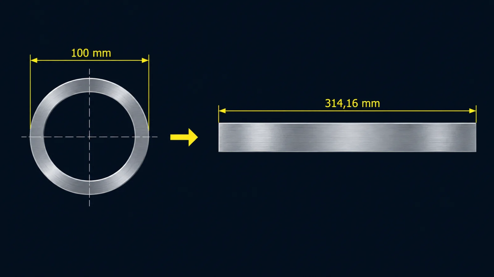
Step 6 — Calculate the developed length of the pipe
Now we need to transform the pipe's circular surface into a flat surface.
The circle will be opened and represented by a straight line.
For a template applied to a finished pipe:
C = π × De
Example
Consider a pipe with:
Outer diameter = 100 mm
So:
C = 3,1416 × 100
C = 314,16 mm
Therefore, the total width of the template that will make a full turn around the pipe will be:
314,16 mm
Step 7 — Divide the development
As we divide the circle into 12 parts, we must also divide the development exactly 12 equal parts.
In our example:
314,16 ÷ 12 = 26,18 mm
Therefore, mark a division every:
26,18 mm
We will have:
0
26,18
52,36
78,54
104,72
130,90
157,08
183,26
209,44
235,62
261,80
287,98
314,16 mm
These positions correspond to the different generators of the pipe.
Step 8 — Raise perpendiculars
In each division of the flat pattern development, lay out a perpendicular line.
Now we will have a sequence of parallel lines.
Each of them will receive the corresponding height that we previously found in the intersection view.
This type of grid is the basis of flat pattern development.
Step 9 — Transfer the heights
Now comes one of the most important steps.
Take the distance from each intersection point to the chosen reference line.
Transfer this same distance to the corresponding generatrix in the development.
For example:
height of point 1 → line 1;
height of point 2 → line 2;
height of point 3 → line 3;
height of point 4 → line 4.
Continue until all points are completed.
The method works because we are bringing to the flat plate the position that each generatrix will have after the material regains its cylindrical shape.
Step 10 — Use the part's symmetry
As we are working with:
pipes of the same diameter;
centralized meeting;
90° angle;
the profile is symmetrical.
Therefore, the points found on one side will appear correspondingly on the other side.
This symmetry is also an excellent way to check the drawing.
If one side of the curve is very different from the other without any geometric difference in the part, there is probably an error in the division or transfer of the measurements.
Step 11 — Join the points
After all the points are marked, join them using a smooth curve.
Do not simply make straight segments from one point to another.
The intersection between the cylinders generates a continuous curve.
To draw it, use:
flexible ruler;
appropriate curve;
or make a smooth hand‑laid connection of the points.
The greater the number of points used in the construction, the easier it will be to faithfully reproduce the curve.
Therefore, although 12 divisions are sufficient for many instructional drawings, increasing the number of divisions can improve the profile definition.
Step 12 — Complete the development
After joining all the points, you will have the developed profile of the pipe end.
The drawing must show a periodic and symmetrical curve.
It is this contour that, after being wrapped around the pipe, will produce the corresponding wolf mouth at the 90° intersection.
If you are creating a template:
cut the profile;
wrap the pipe;
align the ends of the template;
keep the template perpendicular to the axis;
Sketch the entire contour.
Practical example: pipe 100 mm
Let's summarize the calculation for a ready-made pipe with:
External diameter: 100 mm
Angle: 90°
Main pipe diameter: 100 mm
Circumference
C = π × D
C = 3,1416 × 100
C = 314,16 mm
Division into 12 parts
314,16 ÷ 12 = 26,18 mm
Each generatrix of the development will, therefore, be separated by:
26,18 mm
Maximum depth of the wolf mouth
In a perfectly centered theoretical intersection at 90°, with both pipes having exactly the same outer diameter, the maximum cut depth measured between the most advanced point and the most recessed point corresponds to tube radius.
How:
D = 100 mm
we have:
R = D ÷ 2
R = 50 mm
Thus, the theoretical maximum depth of the wolf mouth will be:
50 mm
This value is useful as a layout check.
If the geometric construction of two perfectly identical pipes at 90° produces a depth completely different from this, it is worth checking the drawing.
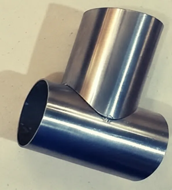
Why is the wolf mouth curve not a simple arc?
This is an important detail.
The wolf mouth should not be drawn simply by choosing a radius and making an arc with a compass.
The profile appears from the intersection of the two cylindrical surfaces.
That's why we built several points.
Each tube generatrix intersects the second cylinder at a different height.
When all these points are connected, the true intersection curve emerges.
The more divisions, the better the layout?
In general, increasing the number of divisions provides more points to define the curve.
For example, you can use:
12 divisions
Simple layout and widely used.
24 divisions
Provides more points and a more detailed curve.
However, it is essential to maintain the correspondence.
If you use 24 divisions in the profile, you must use the same 24 positions in the development.
It doesn’t help to increase the number of points if the divisions are transferred incorrectly.
Common mistakes when laying out a wolf mouth
1. Use the nominal diameter instead of the actual diameter
Pipes may be commercially specified by dimensions that do not correspond directly to the outer diameter.
If you are making a template for an existing pipe, measure the actual outer diameter of the part.
An error in the diameter also changes the template circumference.
2. Confusing outer diameter and mean diameter
They are different situations.
The template that surrounds a finished pipe works on the outer surface.
The development of a plate that will be rolled must consider the thickness and the neutral line.
3. Divide the circumference one way and the development another
The points must match exactly.
If there are 12 positions on the circumference, there must be 12 equivalent positions in the development.
4. Change the order of the points
Numbering the divisions prevents this issue.
5. Join the points with straight lines
The profile must be a continuous curve.
6. Use this layout on pipes of different diameters
The geometry changes.
Even at 90°, a smaller branch joining a larger pipe will have a different profile.
7. Use the same drawing for an inclined branch
If the angle is no longer 90°, the wolf mouth also changes.
8. Ignore an eccentric intersection
When the pipe axes do not intersect at the center, we have another geometric case.
Do pipes of different diameters use the same layout?
No.
The development principle remains related to the intersection of the cylinders, but the points need to be found considering the two actual diameters.
For example:
main pipe of 200 mm;
100 mm branch;
90° intersection.
The cut profile will be different from that obtained for two 100 mm pipes.
There are specific developments for T to 90° of different diameters.
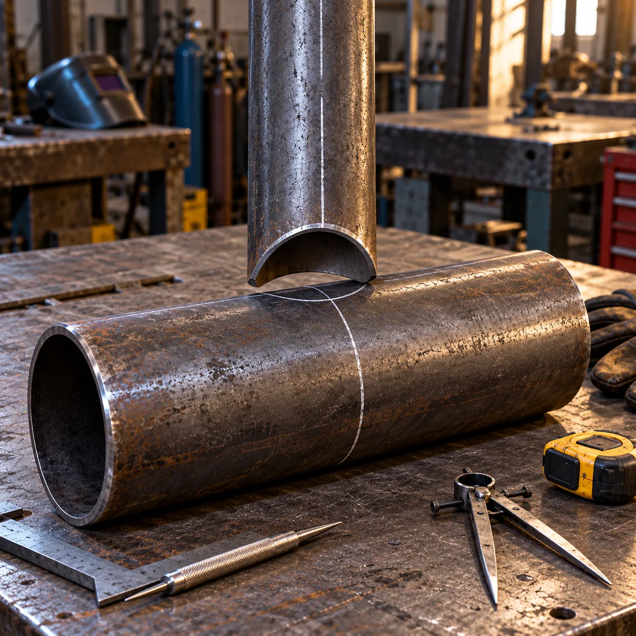
What if the joint is not at 90°?
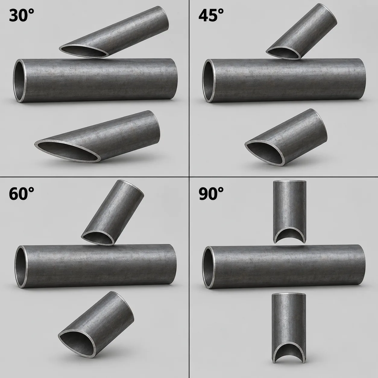
It also changes.
A wolf mouth for:
30°
45°
60°
or any other angle will have a different geometry.
The greater the relative inclination between the pipes, the more the length and the distribution of the points on the profile will differ.
Therefore, before starting any development, always confirm:
main pipe diameter + branch diameter + angle + axis positions.
Centralized and eccentric wolf mouth are the same?
No.
In this article we work with the axes crossing.
When the branch is offset to one side and its axis no longer crosses the central axis of the main pipe, we have an eccentric intersection.
This destroys the symmetry used in the example of this article and requires a different geometric construction.
How to check the layout before cutting?
Before performing the final cut:
check the actual diameter;
check the angle;
check the number of divisions;
check the numbering;
observe the symmetry;
check the total length of the development;
make a template;
wrap the pipe;
check if the ends of the template are aligned;
test the fit before final fabrication.
When possible, making the template first in paper or low‑cost material helps detect errors before transferring the drawing to the final part.
Step-by-step summary
To make a wolf mouth at 90° between pipes of the same diameter:
draw the two pipes at 90°;
lay out the axes;
represent the circular profile;
divide the circumference into equal parts;
number the points;
design the geratrizes;
find the intersection points;
calculate the developed length;
divide the development into the same number of parts;
raise the perpendiculars;
transfer the corresponding heights;
join the points with a smooth curve;
make the template;
check on the pipe itself before cutting.
The secret of this layout is not in memorizing the final shape, but in understanding that each point of the wolf mouth is the result of the geometric intersection between the two cylinders.
Once this logic becomes clear, it becomes much easier to also understand the variations with other diameters, angles and positions.
Important
This article specifically presents the case of two pipes of the same diameter, centered and positioned at 90°. Changing any of these conditions changes the development.
Carry TraceClub in your pocket
Boilermaking layouts, calculations and technical manuals in the palm of your hand — fast, accurate and always with you in the shop or in the field.
- Available for iOS and Android
- Works offline
- PT · EN · ES