
How to lay out a segmented elbow in boilermaking: step by step
Understand how to calculate, divide and develop the segments to fabricate a precise sheet elbow.
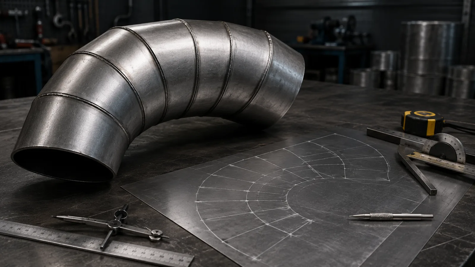
How to lay out a segmented elbow in metal fabrication
The segmented elbow is a widely used solution in metal fabrication to create changes in direction for pipes, ducts, and other cylindrical parts.
Unlike a continuously formed bend, it is constructed from several segments cut at an angle and joined together, progressively forming the desired curvature. This construction is also technically known as a segmented elbow or gored elbow.
For the segments to fit correctly, the layout must primarily consider the part diameter, the total bend angle, the bend radius, and the number of segments.
What is a segmented elbow?
Imagine a straight pipe divided into several small segments. When the ends of these segments are cut at certain angles and then joined, each joint causes a small change in direction.
The sum of these changes forms the complete elbow.
The greater the number of segments used for the same total angle, the smaller the change in direction at each joint tends to be, and the smoother the elbow's geometry becomes. The appropriate number of pieces, however, depends on the design, diameter, application, and manufacturing criteria.
What measurements are needed?
Before starting the layout, it is important to know at least:
pipe or duct diameter;
total elbow angle;
elbow radius;
number of pieces or segments;
plate thickness;
method of joining the segments.
It is also important to check how the technical drawing defines the bend radius and the reference diameter, avoiding mixing internal, external, and centerline measurements.
1. Define the total bend angle
First, determine the change in direction the part needs to make.
For example:
90° elbow
In this case, all segments together should produce a total change in direction of 90°.
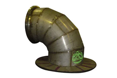
There can also be elbows of 15°, 30°, 45°, 60° or other values defined by the project. Industrial catalogs for segmented elbows present precisely different angle and segment quantity configurations.
2. Determine the number of segments
Next, it is necessary to define how many pieces will form the elbow.
This point is important because the number of segments directly affects the angle of each joint.
Consider, for example, a 90° elbow formed by five pieces.
There are four joints between them:
5 pieces → 4 joints
Distributing the 90° equally:
90° ÷ 4 = 22.5° change of direction per joint
Since each joint is formed by the meeting of two cut faces, in a symmetrical construction each side receives half of this angle:
22.5° ÷ 2 = 11.25°
Therefore, in this example, the corresponding miter cut is 11.25°.
This same principle can be observed in industrial documentation: a 45° elbow formed by three segments has two joints and appears with a miter angle of 11.25°.
Attention: some handouts, workshops, and software use different conventions for counting “segments”, “half-segments”, joints, or pieces. Therefore, the quantity must always be interpreted according to the drawing or method used.
3. Draw the view of the elbow
With the main values defined, represent the elbow in elevation.
Mark:
centerline;
radius;
diameter;
start of the bend;
end of the bend;
position of the joints between segments.
Divide the total angle according to the number of joints defined previously.
This view will be the reference for finding the necessary lengths at each position on the pipe surface.
4. Divide the circumference
To develop the segment on a flat surface, it is first necessary to represent the perimeter of the pipe.
The basic circumference is calculated by:
C = π × D
where:
C = circumference length
D = diameter used as reference
Then, the circumference can be divided into equal parts.
In traditional layout methods, common divisions include:
12 parts or 24 parts
The larger the number of divisions, the more points will be available to construct the cut line.
Layout materials for segmented elbow curves found in boilermaking / metal fabrication use precisely perimeter divisions of 12 or 24 parts to develop the profile.
5. Project the points to the cut line
Draw the circular section of the pipe and mark on it the divisions made earlier.
From those points, project lines to the side view of the segment.
The intersection of these lines with the inclined cut plane provides different heights.
These measurements are the ordinates that will allow reproducing, on the flat sheet, the true line required for the cut.
It is precisely this step that transforms the three-dimensional geometry of the pipe into a two-dimensional drawing that can be marked on the plate.
6. Develop the plate
Now draw a line with a length corresponding to the circumference development.
Divide this line using exactly the same number of parts used previously.
If the circumference was divided into 12 parts, the development must also have 12 divisions.
At each position, transfer the height found in the projection from the previous step.
When all points are positioned, carefully join them to form a continuous line.
This line represents the cut profile of the segment.
7. Repeat or mirror the necessary segments
In a symmetrical elbow, certain segments can share the same geometry, while the end segments may have different characteristics from the intermediate segments.
Therefore, it is not necessary to assume that each piece will necessarily have a completely different development.
In some methods, the intermediate segments use the same pattern, and the two end segments are corresponding or mirrored.
Carry TraceClub in your pocket
Boilermaking layouts, calculations and technical manuals in the palm of your hand — fast, accurate and always with you in the shop or in the field.
- Available for iOS and Android
- Works offline
- PT · EN · ES

8. Check the layout before cutting
Before cutting the plate, check:
total developed length;
number of divisions;
position of each ordinate;
joint angle;
segment direction;
correspondence between pieces;
final radius of the bend.
Also verify if the design requires excess metal for welding, closure or another type of joint.
These allowances must not be added arbitrarily to the geometric calculation of the development.
A common mistake in the layout of segmented elbows
One of the most frequent errors is confusing the joint direction change angle with the cutting angle of each piece.
For example, if a joint needs to produce a direction change of 30°, that does not necessarily mean cutting both pieces at 30°.
In a symmetric joint, each surface contributes half of that inclination.
This detail completely changes the final closure of the curve.
Another mistake: mixing radius and diameter
The diameter represents the size of the pipe's cross‑section.
The bend radius determines the path followed by the centerline during the change of direction.
They are two different measurements.
A curve can have the same diameter and be built with different radii, producing tighter or more open curves.
The more segments, the better?
Not necessarily.
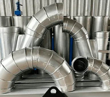
Adding segments can make the change of direction geometrically smoother, but it also increases:
number of cuts;
number of joints;
assembly time;
weld points or closure;
need for dimensional control.
The correct quantity must be defined according to the project and the manufacturing requirements.
The correct layout starts before cutting
The accuracy of a segmented elbow depends far more on planning than on the moment of cutting.
Correctly defining the diameter, radius, angle, number of segments and divisions of the flat pattern development prevents small errors from accumulating to the final segment.
Therefore, mastering plate development remains an important skill for those who work with industrial boilermaking / metal fabrication layout / pattern development.
Carry TraceClub in your pocket
Boilermaking layouts, calculations and technical manuals in the palm of your hand — fast, accurate and always with you in the shop or in the field.
- Available for iOS and Android
- Works offline
- PT · EN · ES