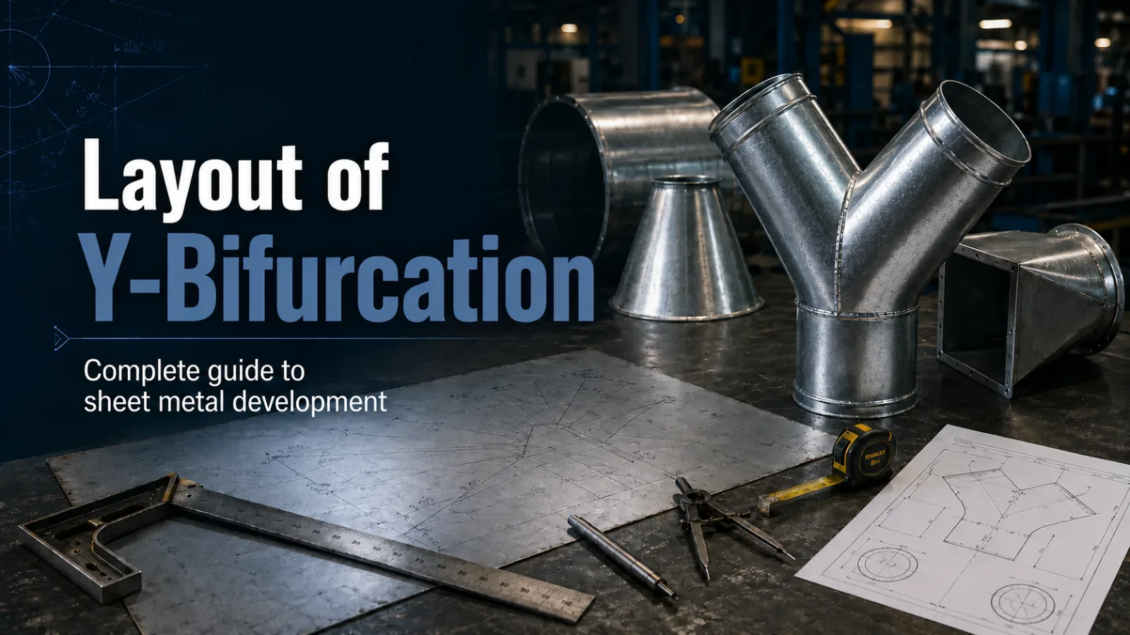
How to lay out a Y-branch in industrial metal fabrication
Understand plate development for Y-branches, their applications, necessary measurements, and precautions to ensure a precise fit between pipes.
How to lay out a Y-branch in industrial metal fabrication
Introduction
The Y-branch is one of the most common components in industrial metal fabrication, especially in ventilation systems, exhaust systems, metal piping, and for conveying gases or particles.
It is used when a flow needs to be divided into two paths or when two flows need to be joined into a single pipe. Therefore, its shape resembles the letter “Y”.
Although it may seem like a simple part once assembled, its plate development requires attention. A small error in the layout can cause gaps, misalignment, difficulty in welding, and material waste.
In this article, you will understand what a Y-branch is, where it is used, what measurements are necessary, and what are the main steps to lay it out correctly.
What is a Y-branch
A Y-branch is a component formed by pipes that meet at an angle.
In practice, it can have two main functions:
To divide the flow from a main pipe into two branches;
To join two branches into a single main pipeline.
This type of fitting is widely used when a smoother diversion than a “T” connection is required. As the pipes meet at an angle, the flow tends to be more directed and less abrupt.
In metal fabrication, the Y-branch can be manufactured from metal plates that are cut, formed, and welded, following a previously calculated flat pattern development.
Where the Y-branch is used
The Y-branch appears in various industrial systems.
Among the most common applications are:
Industrial exhaust systems;
Ventilation ducts;
Metal pipelines;
Systems for transporting powder, grains, or particles;
Hot air networks;
Industrial chimneys;
HVAC ducts;
Air intake and distribution systems.
It is especially useful when the part needs to maintain a more continuous flow, avoiding very aggressive changes in direction.
Why the Y-branch layout requires precision
The Y-branch layout is not just the drawing of two pipes meeting.
It is necessary to correctly develop the intersection between the parts so that the cuts fit together during assembly.
When the layout is poorly done, problems such as the following may arise:
Irregular fitting opening;
Lack of contact between pipes;
Excessive gap for welding;
Deformation during assembly;
Plate waste;
Increased rework;
Out-of-spec part.
Therefore, before cutting the plate, it is essential to correctly define the measurements, angles, and development method.
Measurements needed to lay out a Y-branch
Before starting the layout, it is necessary to gather the main information about the part.
The most important measurements are:
Main pipe diameter;
Branch pipe diameter;
Main pipe length;
Branch pipe length;
Bifurcation opening angle;
Plate thickness;
Material type;
Weld gap, when necessary;
Manufacturing tolerances;
Exact position of the intersection between pipes.
These measurements can come from a technical drawing, a 3D model, or from a measurement taken directly at the installation site.
How Y-branch development works
The development of a Y-branch consists of transforming the three-dimensional part into a flat pattern.
This drawing will be laid out on the plate to guide cutting, forming, and assembly.
In a Y-branch, the main challenge lies in the intersection region between the pipes. This region needs to be developed precisely so that the branch fits correctly into the main pipe.
Generally, the process involves:
Dividing the perimeter of the pipes into equal parts;
Projecting the intersection points;
Transferring the heights to the flat pattern development;
Joining the points to form the cutting line;
Check symmetry, angles, and fit;
Prepare the part for cutting and assembly.
Basic step-by-step for laying out a Y-branch
Below is an overview of the process. The method may vary depending on the type of branch, the angle, and the pattern used in the workshop.
1. Define the main pipe and branches
The first step is to identify which will be the main pipe and which will be the branches.
The main pipe is the central part of the branch. The branches are the outlets or inlets that connect to it.
It is important to define:
Whether the part will divide or join the flow;
What is the diameter of each pipe;
What will be the angle between the branches;
Whether the branches will have the same diameter or different diameters.
This definition prevents errors when calculating the development.
2. Divide the pipe perimeter
After defining the dimensions, the pipe perimeter must be divided into equal parts.
This division serves to create reference points along the circumference.
The greater the number of divisions, the more accurate the development will be.
Example of common divisions:
8 parts;
12 parts;
16 parts;
24 parts.
For larger parts or those requiring higher precision, it is recommended to use more divisions.
3. Design the intersection between the pipes
With the pipes divided, the next step is to design the meeting line between the branch and the main pipe.
This line represents the actual cut shape that will be made so that one part fits into the other.
In practice, this step requires attention because the intersection changes according to:
The bifurcation angle;
The pipe diameter;
The branch position;
The type of joint;
The inclination of the part.
This is one of the most important parts of the layout / pattern development.
4. Transfer the points to the flat pattern development
After locating the intersection points, they are transferred to the flat pattern development of the plate.
The objective is to transform the curved surface of the pipe into a flat area.
At this point, each projected point indicates a specific height or distance on the drawing.
These points must be marked accurately to form the correct cutting line.
5. Join the cut line points
With all points transferred, they need to be joined smoothly.
This joint forms the outline of the bifurcation mouth.
The line must not be made in just any way. It needs to follow the curve’s behavior, avoiding sharp corners or irregular markings.
A poorly laid out line can cause fit failure and make welding difficult.
6. Check the layout
Before cutting the plate / sheet, check the entire development.
Check:
If the dimensions are correct;
If the number of divisions was maintained;
If the points were transferred correctly;
If the branch angle is correct;
If the length of the part is adequate;
If there is clearance for weld, when necessary;
If the layout is consistent with the technical drawing.
This check prevents material loss and rework.
7. Cut, as per and assemble the part
After checking the layout, the plate can be cut.
After cutting, the part undergoes forming, which may be rolled, calendered, or adjusted to the desired shape.
During assembly, the fit-ups must be tested before the final weld.
A good layout facilitates this step, as the part already arrives close to the required final shape.
Common mistakes in Y‑branch layout
Some errors are very common during the development of this type of part.
Among them are:
Measure only the outer diameter and ignore the plate thickness;
Use few divisions on the perimeter;
Do not check the actual angle of the bifurcation;
Transfer points misaligned;
Score the plate without reviewing the calculation;
Do not consider gap for weld;
Cut before validating the development;
Confusing the inner and outer side of the part.
These errors can compromise the fit and increase manufacturing time.
Tips to improve the layout of the Y Branch
To achieve a more accurate result, follow some best practices:
Always use measuring instruments in good condition;
Check the dimensions before starting the development;
Work with equal divisions on the perimeter;
Identify all the points on the drawing;
Mark references on the plate;
Avoid improvising bends without reference to the laid out points;
Perform a check before cutting;
Whenever possible, use digital tools to reduce errors.
Precision in layout starts before cutting. The better the preparation, the less rework will be required during assembly.
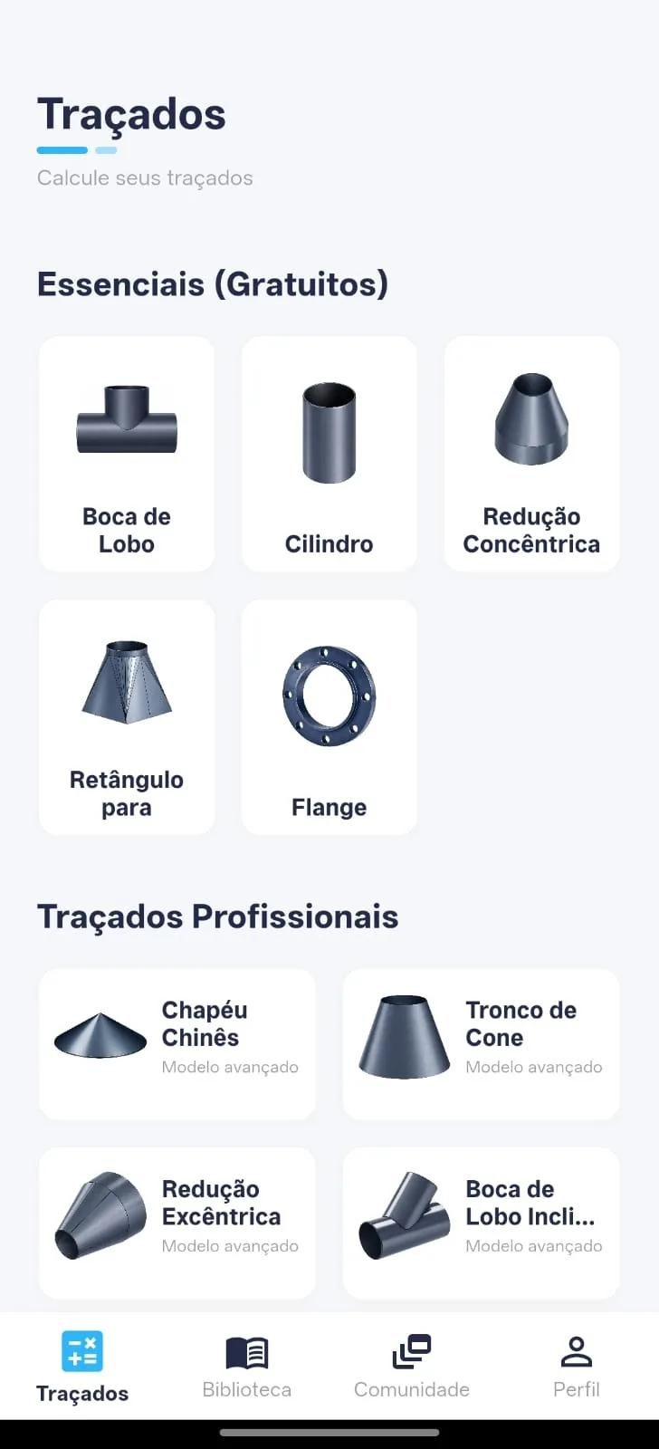
How TraceClub helps in the layout / pattern development of boilermaking / metal fabrication
TraceClub was developed to facilitate the work of those who need to perform industrial boilermaking layout with greater speed and precision.
Instead of relying solely on manual calculations, tables and drawings created from scratch, the app helps generate references for the development of metal parts.
Thus, the professional can save time, reduce errors, and have greater confidence when preparing the plate for cutting and assembly.
For parts such as Y branch, eccentric cone, conical saddle and transitions, having a digital tool can make the process much more practical.
Conclusion
The Y branch is a very important component in industrial boilermaking / metal fabrication, especially in duct systems, exhaust and metal pipework.
Your layout / pattern development requires attention because it involves the intersection between pipes at an angle. To ensure the fit is correct, it is necessary to measure well, divide the perimeter, lay out the points, transfer the development to the plate / sheet and check everything before cutting.
Mastering this process helps produce more precise parts, reduce waste, and improve assembly quality.
In upcoming articles, we will delve into other types of development, such as eccentric cone, conical pipe and rectangle to round.
If you work in industrial boilermaking / metal fabrication and want to make your layouts faster and safer, follow TraceClub and see how technology can help in the daily workshop.
Carry TraceClub in your pocket
Boilermaking layouts, calculations and technical manuals in the palm of your hand — fast, accurate and always with you in the shop or in the field.
- Available for iOS and Android
- Works offline
- PT · EN · ES