How to lay out square-to-round transitions in metal fabrication: complete step-by-step guide
Learn to develop a square-to-round transition using the triangulation method, from initial measurements to plate marking.
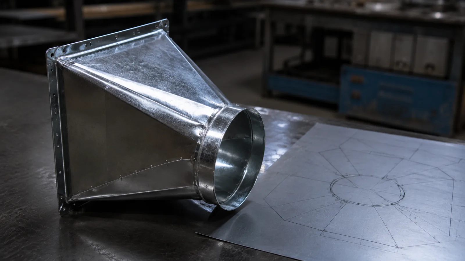
What is a square-to-round transition?
A square-to-round transition is a component used to connect a square or rectangular outlet to circular piping.
This type of component is very common in the fabrication of ducts, ventilation systems, exhaust fans, industrial equipment, silos, hoods, and piping.
To correctly fabricate this transition, the boilermaker needs to develop the surface of the part on a flat plate. This process is known as layout, development, or flat pattern development.
The most common method for this type of part is the triangulation method.
Where is the square-to-round used?
The square-to-round transition can be found in different industrial applications, such as:
Ventilation systems;
Exhaust ducts;
Industrial hoods;
Material transport pipelines;
Storage equipment;
Silos and tanks;
Dust collection systems;
Industrial air conditioning installations.
The function of the part is to allow the flow to pass gradually from a square or rectangular section to a circular section.
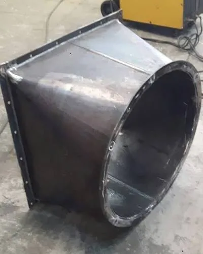
What measurements are needed?
Before starting the layout, it is necessary to correctly determine the dimensions of the part.
The main measurements are:
Width of the square or rectangular base;
Length of the square or rectangular base;
Diameter of the round outlet;
Total height of the transition;
Position of the circular outlet;
Plate thickness;
Margin for welding or closing.
It is also important to check whether the part will be concentric or eccentric.
In a concentric transition, the center of the circular outlet is aligned with the center of the square base.
In an eccentric transition, the circular outlet is offset to one side.
This offset modifies the measurements of the lines used in the development.
What is the triangulation method?
The triangulation method consists of dividing the part's surface into several triangles.
Each triangle has its own measurements, which must be found before being transferred to the plate.
The process normally involves:
Dividing the circumference of the round outlet;
Connecting the points of the circumference to the corners and divisions of the base;
Finding the true lengths of the lines;
Constructing the triangles on the plate;
Forming the complete development of the part.
The greater the number of divisions of the circumference, the smoother and more precise the transition tends to be.
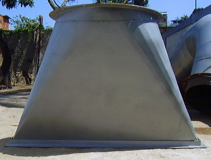
Step-by-step layout of square to round transition
1. Draw the top view
Start by drawing the square or rectangular base to the correct dimensions.
Then, draw the circumference of the round outlet in the position it will occupy on the part.
In a concentric transition, the circumference must be centered relative to the base.
In an eccentric transition, it must be positioned according to the offset defined in the design.
2. Divide the circumference
Divide the circumference into equal parts.
You can use 8, 12, 16 or more divisions, depending on the size of the part and the desired precision.
After dividing the circumference, number all points in sequence. This numbering helps to avoid errors during the development construction.
3. Connect the points to the base
Connect the points on the circumference to the corners and corresponding points on the square base.
These connections will form the triangles that represent the transition surface.
It is important to maintain the same sequence of points throughout the process.
4. Draw the side view
In the side view, mark the total height of the transition.
The side view will be used to find the true length of the inclined lines.
Measurements observed only in the top view may be shortened due to the inclination of the part. Therefore, it is necessary to find the true lengths.
5. Find the true lengths
To find the true length of each line, use:
The horizontal distance found in the top view;
The height of the transition;
The construction of a right triangle.
The hypotenuse of this triangle represents the true length of the inclined line.
This process must be repeated for all lines that have different lengths.
In a concentric and symmetrical part, some lines may have the same measurement. However, in an eccentric part, there is usually a greater number of different measurements.
6. Start the development on the plate
Choose a reference line to begin the development.
Mark the first segment corresponding to the circumference division.
Then, using a compass or other marking tool, transfer the true lengths found previously.
Each new point will be located by the intersection of two arcs.
7. Construct the triangles
Continue constructing the triangles one next to the other, following the numbering defined on the circumference.
It is important not to alter the sequence of points, as this can completely deform the development.
Repeat the process until the entire circumference of the part is completed.
8. Lay out the cutting lines
After locating all the points, join them using straight lines or a smooth curve, according to the geometry of the part.
The line corresponding to the circular outlet usually presents a sequence of small segments.
The greater the number of divisions, the closer this region will be to a perfect curve.
9. Add the weld margin
Before cutting the plate, add the necessary allowance for closing and welding.
This allowance may vary according to:
Plate thickness;
Welding process;
Type of joint;
Equipment used;
Company manufacturing standard.
Possible allowances for bending, flanging, or fitting should also be considered.
10. Check all measurements
Before cutting, check:
Base width and length;
Outlet diameter;
Part height;
Point sequence;
True sizes;
Weld margin;
Circular outlet position;
Development symmetry.
Performing this check before cutting reduces material waste and avoids rework.
Main layout errors
Dividing the circumference incorrectly
The divisions must be the same size. Irregular divisions can deform the round output.
Changing the point sequence
The numbering must follow the same order in all stages of the layout.
Swapping two points can change the entire shape of the part.
Using projected dimensions as actual dimensions
The inclined lines need to be calculated at true size.
Directly using a dimension from the top view can result in a part smaller or larger than required.
Forgetting the weld margin
The geometric development represents the part's surface, but fabrication may require an additional margin for closure.
Do not consider the plate thickness
In small parts or those made with thicker plates, the material thickness can affect the final result.
Make few divisions on the circumference
A very small number of divisions can make the round outlet look faceted.
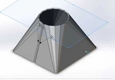
How to improve the accuracy of the layout?
To achieve a more accurate result:
Use calibrated measuring instruments;
Always work with the same unit;
Number all points;
Make the auxiliary lines with a thin dash;
Check the base diagonals;
Avoid rounding measurements before the final stage;
Check the true magnitudes;
Create a reduced model when the part is complex;
Consider the plate thickness;
Confirm the dimensions before cutting.
On large parts, a small error in the layout can cause a significant difference during assembly.
Manual layout or automated calculation?
Manual layout is important for understanding the part geometry and continues to be used in many shops.
However, the process can require a considerable amount of time, especially when there are many dimensions, sections, or offsets.
A calculation tool can help to:
Reduce development time;
Standardize the calculations;
Avoid numbering errors;
Obtain measurements more quickly;
Reduce sheet waste;
Facilitate the inspection of the part.
In TraceClub, the professional can use resources aimed at calculations and layout / pattern development for boilermaking / metal fabrication, making part preparation faster and more practical.
Conclusion
The layout from square to round is one of the most important developments in boilermaking / metal fabrication.
To manufacture the part correctly, it is necessary to measure the base, define the outlet diameter, divide the circumference, find the true dimensions and construct the development using the triangulation method.
Attention to the sequence of points, the inclined lines and the manufacturing margins is essential to avoid errors.
With a well-executed process, it is possible to produce a precise transition, reduce material waste, and facilitate the assembly of the part.
Carry TraceClub in your pocket
Boilermaking layouts, calculations and technical manuals in the palm of your hand — fast, accurate and always with you in the shop or in the field.
- Available for iOS and Android
- Works offline
- PT · EN · ES