How to lay out a concentric reducer step by step
Learn to calculate and develop a concentric reducer on the plate with formulas, a practical example, and guidelines to avoid errors.
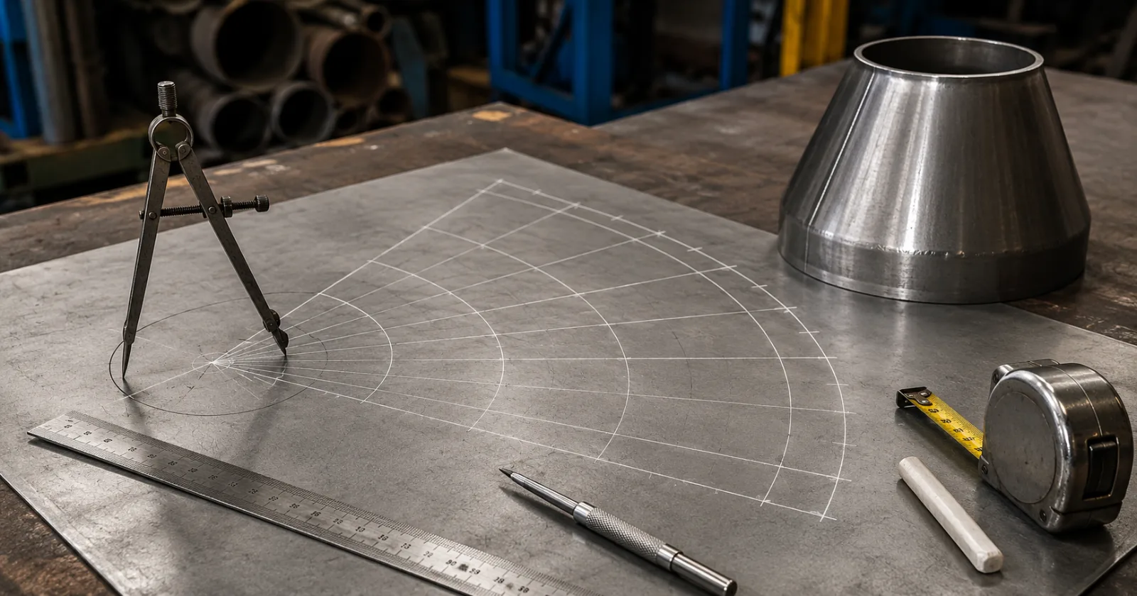
A concentric reducer is a component widely used in metal fabrication to join pipes, ducts, or equipment with different diameters, keeping both ends aligned on the same axis.
Although it may seem like a complex part, its development can be done simply when measurements and formulas are applied correctly.
In this guide, you will learn how to calculate and lay out a concentric reducer directly on the plate.
What is a concentric reducer?
A concentric reducer has one larger end and one smaller end, with the centers of the two circles aligned.
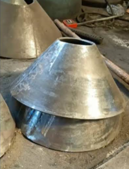
Its shape corresponds to a truncated cone. When this surface is opened and laid flat on a plate, the result is a circular sector formed by:
An outer arc;
An inner arc;
Two side lines;
An angular opening.
This development is then cut, rolled, and closed to form the reducer.
Important: This method is only for concentric reducers. When the centers of the ends are offset, the part is an eccentric reducer and requires a different layout method.
Required Measurements
Before starting, separate the three main measurements of the reducer:
D: larger diameter;
d: smaller diameter;
h: reducer height.
It will also be necessary to calculate:
R: larger radius;
r: smaller radius;
g: reducer generatrix;
L: outer radius of the development;
l: inner radius of the development;
α: sector angle.
All measurements must be in the same unit, usually millimeters.
Pay attention to plate thickness
Check if the diameters provided in the project are internal, external, or mean.
For thicker plates, the development should normally consider the mean line of the thickness. In this case:
Mean diameter = outer diameter − thickness
Or:
Average diameter = inside diameter + thickness
Always follow the measurements and criteria defined in the project's technical drawing.
1. Calculate the radii
The radius corresponds to half of the diameter.
Larger radius
R = D ÷ 2
Smaller radius
r = d ÷ 2
These values will be used in subsequent calculations.
2. Calculate the generatrix
The generatrix is the inclined distance between the larger end and the smaller end of the reducer.
It should not be confused with the vertical height of the part.
The formula is:
g = √[h² + (R − r)²]
Where:
g: generatrix;
h: reducer height;
R: major radius;
r: minor radius.
The difference between the radii represents the horizontal displacement between the two ends.
3. Calculate the outer radius of the development
The outer radius is the distance between the theoretical vertex of the complete cone and the arc corresponding to the major diameter.
The formula is:
L = (g × R) ÷ (R − r)
It is also possible to calculate directly using the diameters:
L = (g × D) ÷ (D − d)
4. Calculate the inner radius of the development
The inner radius corresponds to the distance between the same theoretical vertex and the arc of the smaller diameter.
The formula is:
l = (g × r) ÷ (R − r)
Using the diameters:
l = (g × d) ÷ (D − d)
After the calculation, perform the following check:
L − l = g
The difference between the outer radius and the inner radius must be exactly equal to the reducer's slant height.
5. Calculate the sector angle
The angle determines how much of the circle will be used to form the development.
The formula is:
α = 360° × (R − r) ÷ g
Using the diameters:
α = 180° × (D − d) ÷ g
The result will be the angle that must be marked between the two side lines of the development.
Practical example of concentric reducer
We will calculate a reducer with the following dimensions:
Larger diameter: 600 mm;
Minor diameter: 300 mm;
Height: 400 mm.
Step 1: calculate the radii
R = 600 ÷ 2
R = 300 mm
r = 300 ÷ 2
r = 150 mm
Step 2: calculate the generatrix
g = √[400² + (300 − 150)²]
g = √[160.000 + 22.500]
g = √182.500
g = 427,20 mm
Step 3: calculate the outer radius
L = (427,20 × 300) ÷ (300 − 150)
L = 128.160 ÷ 150
L = 854,40 mm
Step 4: calculate the internal radius
l = (427,20 × 150) ÷ (300 − 150)
l = 64.080 ÷ 150
l = 427,20 mm
Step 5: calculate the angle
α = 360° × 150 ÷ 427,20
α = 126,40°
Result of the development
To lay out this reduction on the plate, use:
External radius: 854,40 mm;
Inner radius: 427,20 mm;
Sector angle: 126,40°;
Distance between the arcs: 427,20 mm.
The distance between the two arcs corresponds to the piece's generatrix.
How to mark the concentric reducer on the plate
With the calculations completed, the development can be transferred to the plate.
1. Define the center of the development
Mark a point that will be used as the center of the two arcs.
This point represents the theoretical vertex of the full cone. Depending on the dimensions of the reducer, it may lie outside the plate.
2. Lay out an initial line
Starting from the centre, lay out a straight line longer than the calculated outer radius.
This will be the first side of the reducer.
3. Lay out the outer arc
Using a compass, radius bar or tape measure fixed at the center, mark the arc using the outer radius value.
In the example:
Outer radius = 854,40 mm
4. Lay out the inner arc
Without changing the central point, lay out the second arc with the inner radius.
In the example:
Inner radius = 427,20 mm
5. Mark the angle
Starting from the first line, mark the calculated angle with a protractor, template or geometric method.
In the example:
Angle = 126,40°
6. Lay out the second side
Connect the angle marking to the center of the development.
Now the geometric shape of the reduction is complete.
7. Add the fabrication margins
Only after completing the geometric layout, add the necessary margins for:
Welding;
Overlap;
Bend;
Flange;
Finish;
Assembly adjustment.
The width of these margins depends on the manufacturing process and the project specifications.
How to check the layout before cutting
Before cutting the plate, perform some checks.
Check the distance between the arcs
The difference between the radii must equal the generatrix:
L − l = g
In the example:
854,40 − 427,20 = 427,20 mm
Check the outer arc
The length of the outer arc must be equal to the circumference of the larger diameter:
C = π × D
In the example:
C = 3,1416 × 600
C = 1.884,96 mm
Check the inner arc
The inner arc must be equal to the circumference of the smaller diameter:
C = π × d
In the example:
C = 3,1416 × 300
C = 942,48 mm
These checks help identify errors before cutting and prevent material waste.
Tools used in layout / pattern development
To perform manual development, the following are usually used:
Tape measure;
Metal ruler;
Square;
Scribe;
Dry-point compass;
Radius bar;
Protractor;
Punching;
Scientific calculator;
Line or weld bead for large radii.
In larger parts, the center of the development may be distant or outside the plate. In such cases, a radius bar or a line attached to the central point facilitates the marking of the arcs.
Common errors in layout
Using the height instead of the generatrix
The height is measured vertically, while the generatrix follows the piece’s inclination. Using the height to lay out the arcs will result in a development smaller than required.
Confusing radius with diameter
Before applying the formulas, confirm whether the value used corresponds to the radius or the diameter.
Mixing internal and external diameters
Using an internal diameter on one end and an external diameter on the other changes the inclination and compromises the fit of the part.
Add the weld margin before calculation
First perform the geometric development. The fabrication margins should be added only afterwards.
Do not check the lengths
Checking the arcs and the generatrix is a simple step that can prevent the loss of an entire plate.
Use this method on an eccentric reducer
The concentric reducer has aligned centers and a constant generator around the entire circumference. The eccentric reducer is asymmetrical and is normally developed using the triangulation method.
After cutting
After cutting the development:
Remove burrs and irregularities;
Mark the center line of the part, when necessary;
Perform the forming gradually;
Check the two diameters during the rolling;
Align the joint ends;
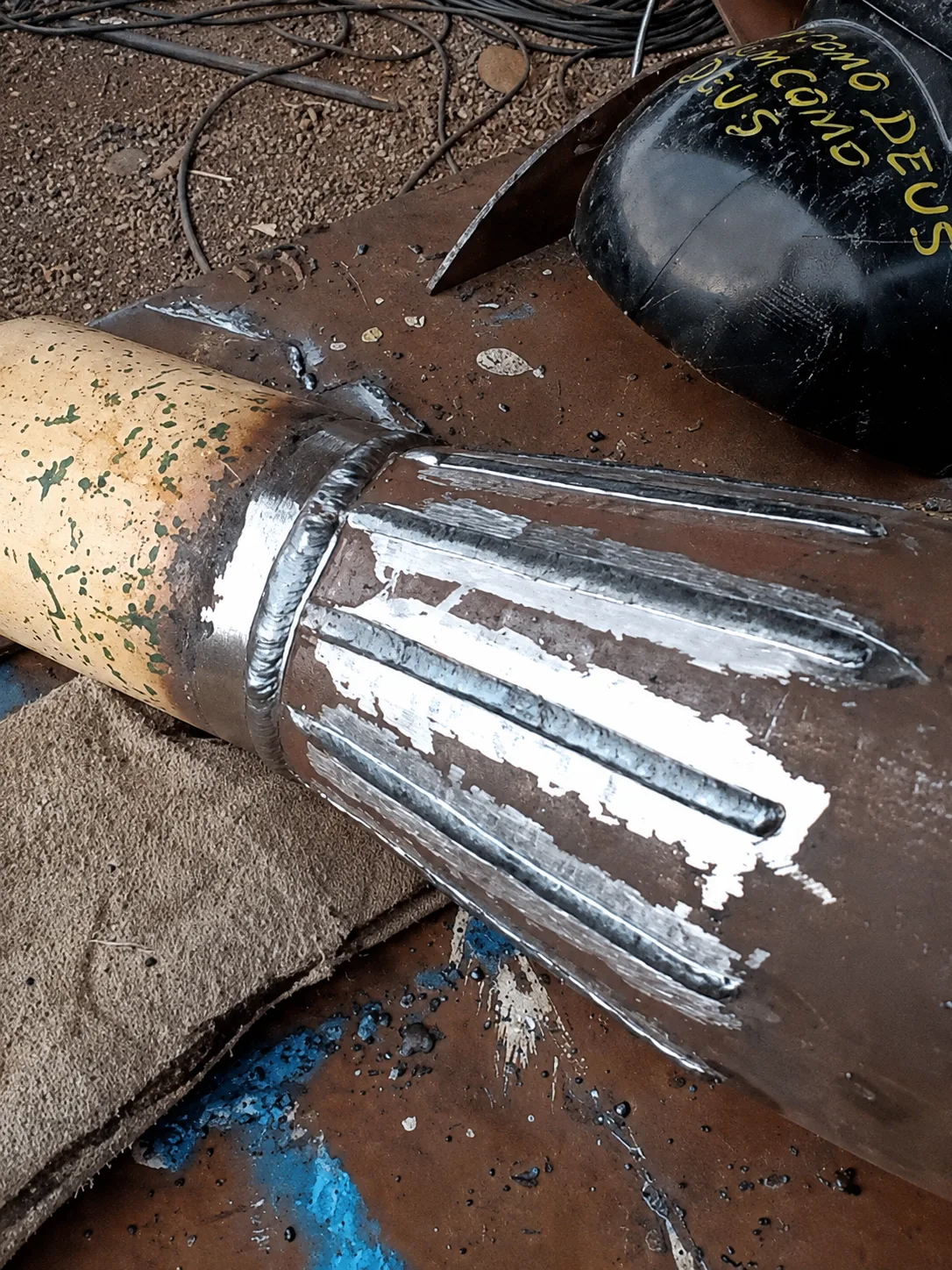
Make the tack welds;
Check the square, the height and the roundness;
Finalize the welding according to the project procedure.
Avoid completing all the welding without first checking the diameters, as thermal contraction can deform or ovalize the reducer.
Conclusion
To correctly lay out a concentric reducer, it is necessary to calculate the generatrix, the development radii, and the sector angle.
The process can be summarized as:
Identify the diameters and the height;
Calculate the radii;
Find the generatrix;
Calculate the external and internal radii;
Determine the angle;
Mark the arcs on the plate;
Add the fabrication margins;
Check the dimensions before cutting;
Cut, form and assemble the part.
With correct calculations and a good verification, it is possible to fabricate the reducer with greater precision, reduce waste and avoid rework during assembly.
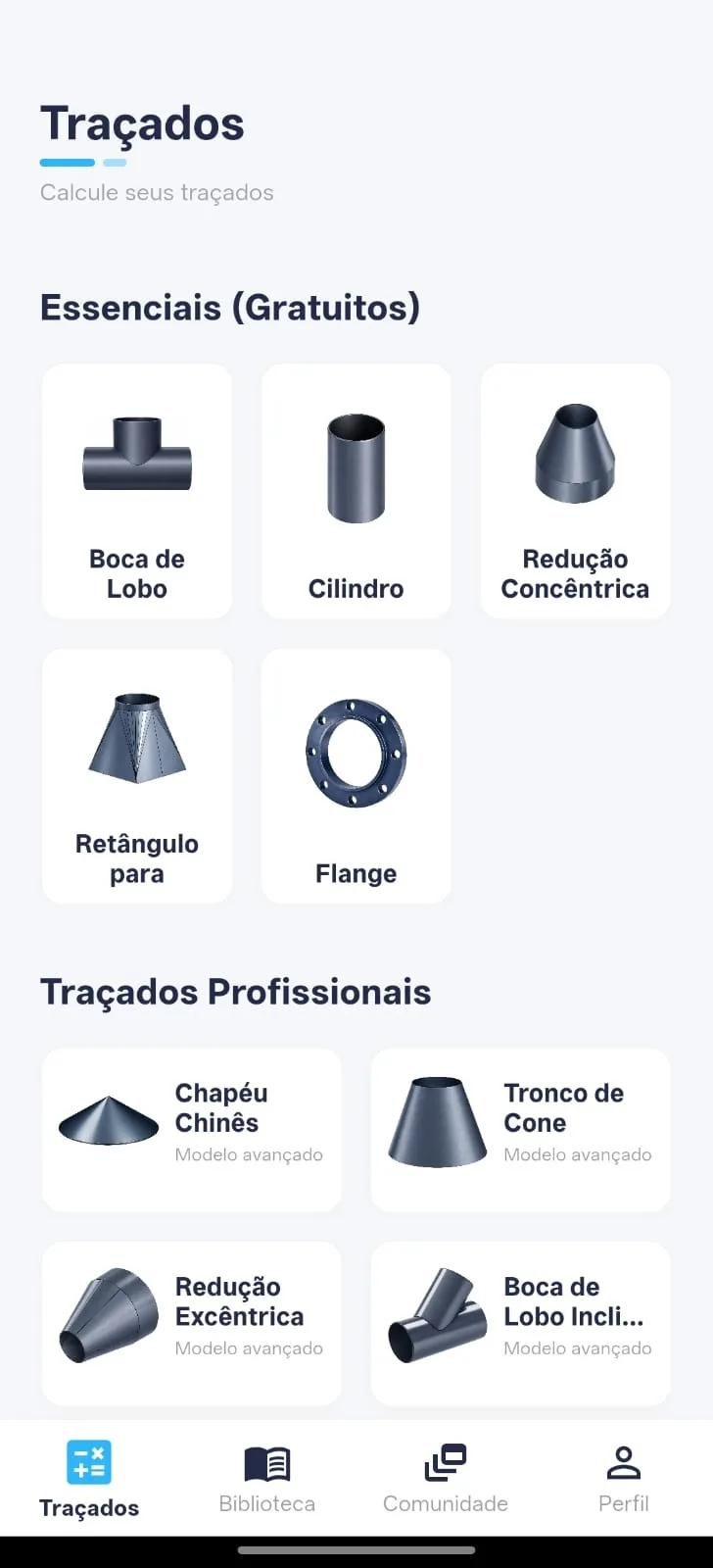
TraceClub brings together calculations and tools to simplify boilermaking layout development directly on the phone, even during work in the workshop or in the field.
Carry TraceClub in your pocket
Boilermaking layouts, calculations and technical manuals in the palm of your hand — fast, accurate and always with you in the shop or in the field.
- Available for iOS and Android
- Works offline
- PT · EN · ES