
How to lay out an eccentric reducer in metal fabrication
Learn the step-by-step process to develop an eccentric reducer using the triangulation method and correctly prepare the template for plate cutting.
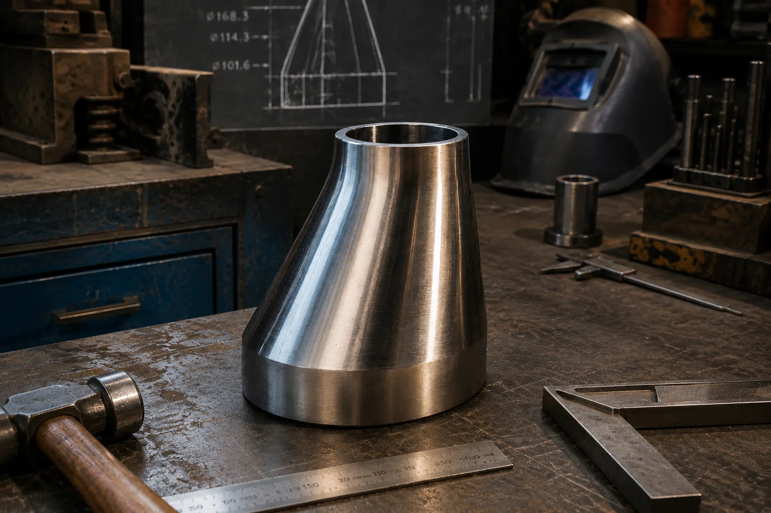
In metal fabrication, not every transition between two diameters can be developed as a common cone. When the center of the smaller opening is offset from the center of the larger opening, we have an eccentric reducer, and this offset completely changes the geometry of the part's generatrices.
To lay out correctly, it's not enough to calculate two circumferences and join them. It's necessary to represent the part in plan and elevation, divide its circumferences, determine the measurement lines, and find the true lengths before transferring the geometry to the plate.
In this article, we will understand how this development works and how to perform the layout using the triangulation method.
What is an eccentric reducer?
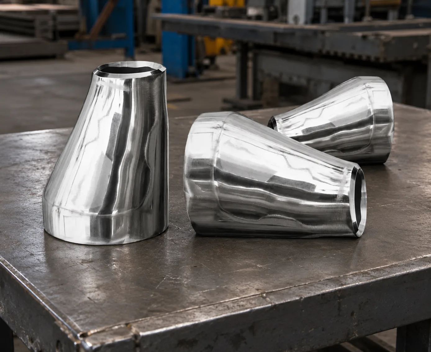
An eccentric reducer is a transition used to connect two circular sections of different diameters whose centers are not positioned on the same axis.
Imagine a reducer with:
larger diameter: 500 mm;
smaller diameter: 300 mm;
height: 400 mm.
If the two diameters are perfectly centered, we will have a concentric reducer.
Now, if we shift the 300 mm circle laterally, the transition becomes eccentric.
When the part is fully eccentric and we want to keep one side aligned, the offset between the centers is:
E = (D − d) ÷ 2
Where:
E = eccentricity
D = larger diameter
d = smaller diameter
In our example:
E = (500 − 300) ÷ 2
E = 100 mm
Therefore, by shifting the center of the smaller opening by 100 mm, one side of the reducer will be aligned.
The same geometric relationship appears in technical piping references to determine the difference between the centerlines of an eccentric reducer.
Why is the layout of an eccentric reducer different?
In a straight cone or a concentric reducer, there is symmetry around a central axis.
In an eccentric reducer, this condition disappears.
Observe conceptually:
Concentric reducer
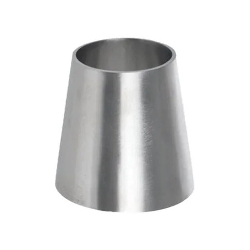
The two centers remain on the same axis.
Eccentric reducer
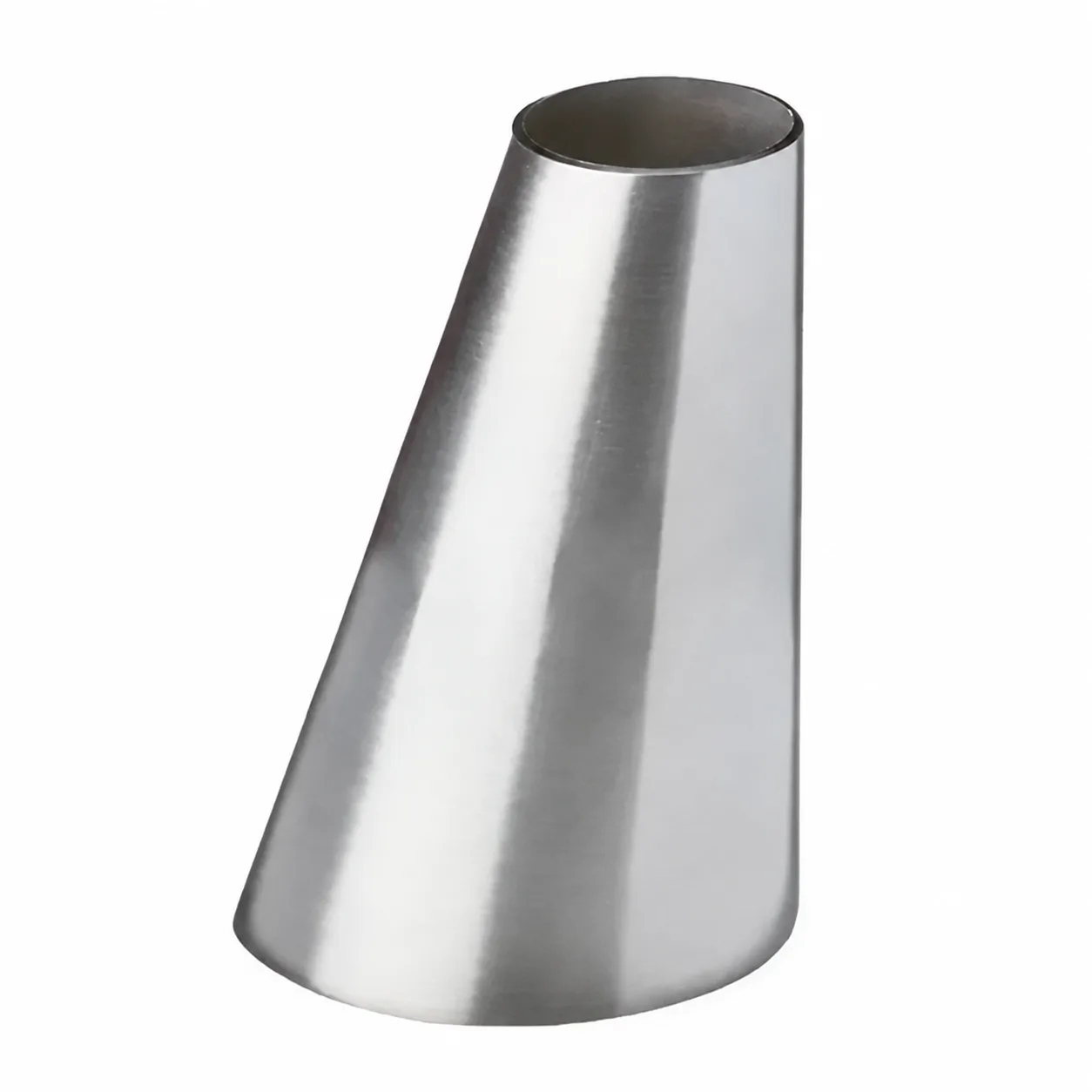
On one side of the part, the transition can be very small. On the opposite side, it will be much larger.
Consequently, the generatrices do not all have the same length.
It is precisely this difference that we need to discover during the layout.
What measurements do you need to have before starting?
To develop an eccentric reducer, have at least four pieces of information:
Measurement | Meaning |
|---|---|
D | Larger diameter |
d | Smaller diameter |
H | Height of the reduction |
E | Eccentricity or offset between centers |
In addition to these dimensions, in actual fabrication the assembly conditions must also be considered later, as:
plate thickness;
type of joint;
weld margin;
overlap, when applicable;
edge finishing;
manufacturing tolerances.
These clearances should not be confused with the geometric dimensions of the development. First the geometry of the part is determined; then the margins required by the manufacturing process are applied.
Which method to use to develop an eccentric reducer?
There is an important difference here.
For some eccentric reducers of the type flat back / oblique cone, it is possible to use development by radial lines, provided the geometry allows determining a common vertex by extending the side lines.
Already for a offset circular transition, triangulation is especially useful because it allows transforming an irregular surface into a sequence of small triangles whose sides can be determined individually. Technical development materials for plates present both procedures for eccentric reducers.
In this article we will work with the triangulation, for being a method applicable to a wide variety of eccentric transitions.
How does the triangulation method work?
The idea is relatively simple.
Imagine that the entire surface of the reducer is divided into several narrow triangles.
Instead of trying to open the entire surface at once, we determine the actual dimensions of those triangles and then reconstruct them on the plate.
The problem is that, looking at the part only from the plan or elevation, some lines appear shortened by the projection.
Therefore, we need to find their true lengths.
This is one of the foundations of development by triangulation.
Carry TraceClub in your pocket
Boilermaking layouts, calculations and technical manuals in the palm of your hand — fast, accurate and always with you in the shop or in the field.
- Available for iOS and Android
- Works offline
- PT · EN · ES
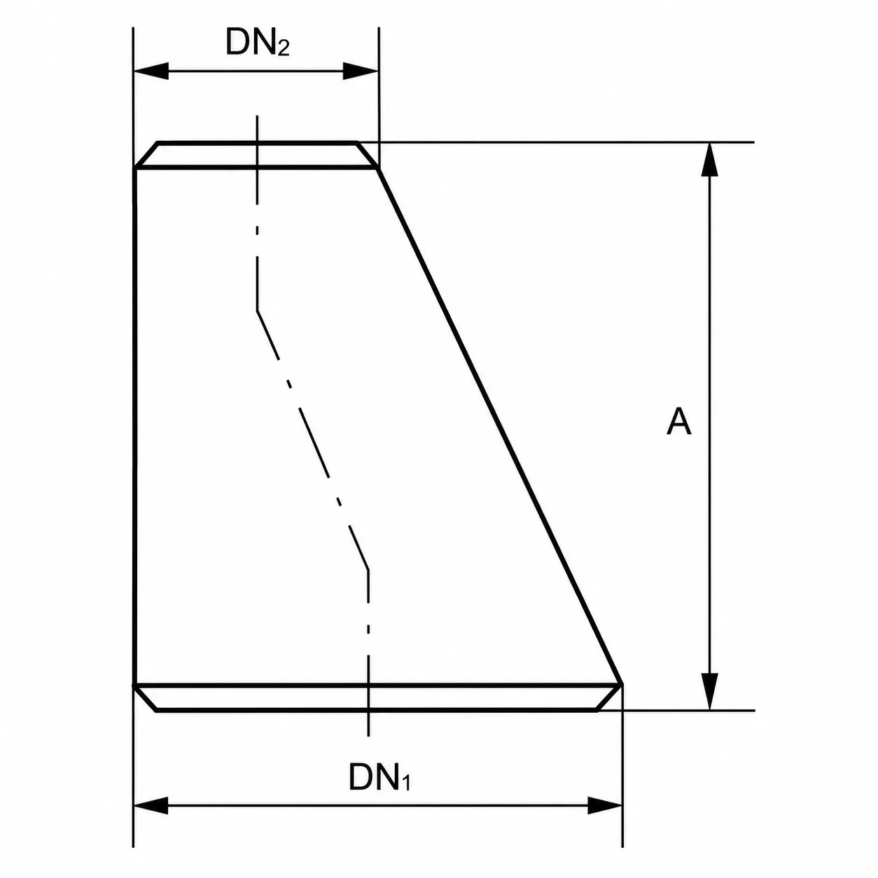
Step 1 — Create the elevation of the reducer
Start by drawing the part at the desired scale.
Using our example:
D = 500 mm
d = 300 mm
H = 400 mm
E = 100 mm
Make the larger diameter first.
Then, at a distance of 400 mm, draw the smaller diameter offset 100 mm relative to the axis of the larger one.
Thus you will have the side view of the reducer.
This view allows immediate visualization:
shorter side;
longer side;
piece height;
direction of the eccentricity.
Step 2 — Build the plan view
Now make the representation of the two circles.
The larger circle will have:
Ø 500 mm
The smaller circle:
Ø 300 mm
The centers will be spaced by:
100 mm
This top view is essential because it is there that we will identify the actual positions of the points of the two circles.
Step 3 — Divide the circles
A classic procedure is to divide each circle into 12 equal parts.
The specific technical material on eccentric reducer development by triangulation precisely uses the division of the two circles into 12 equal parts to construct the measurement lines.
You will have points such as:
1, 2, 3, 4, 5, 6... 12
on the larger circumference and the corresponding points on the smaller one.
The greater the number of divisions, the better the geometric approximation of the curve during manual development, but it also greatly increases the layout work.
Step 4 — Do not confuse arc with rope
This is an important detail in manual layouts.
When using the compass to transfer a distance between two consecutive points on the circle, you are working with a rope, and not with the arc length.
For a circle divided into n parts, the rope can be calculated by:
C = 2R × sin(180° ÷ n)
For the larger diameter of the example:
R = 250 mm
n = 12
Then:
C ≈ 129,4 mm
For the smaller diameter:
R = 150 mm
C ≈ 77,6 mm
These dimensions represent the straight distance between consecutive points of a division into 12 parts.
In a manual layout, they can usually be obtained directly from the drawing with a compass.
Step 5 — Construct the measurement lines
After dividing the two circles, connect the required points according to the triangulation sequence.
These lines will form a kind of mesh over the imaginary surface of the reducer.
Simplifying:
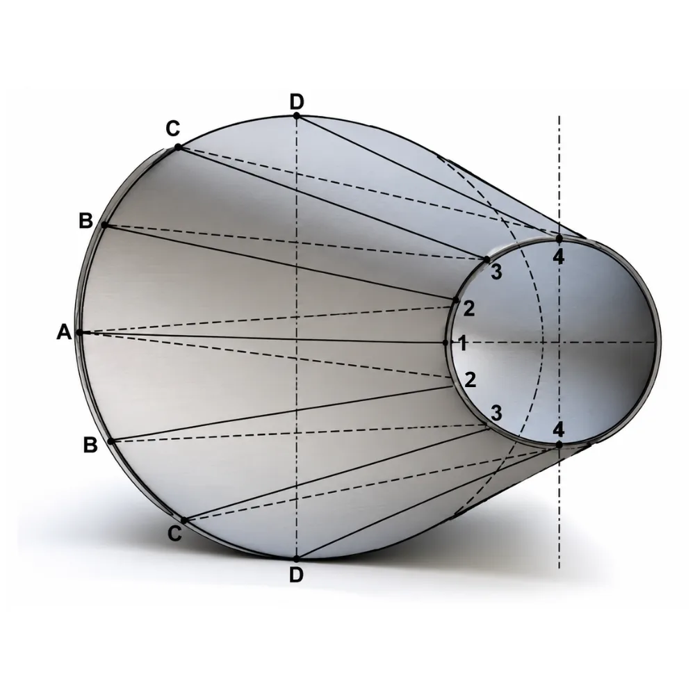
Each small set represents a triangle that will later be reconstructed in the development.
It is important to maintain a logical numbering because it will be used throughout the layout / pattern development.
If you lose the correspondence between the points of the plan and the development, the template will be incorrect.
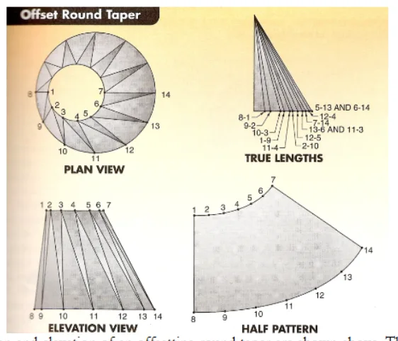
Step 6 — How to find the true lengths
After drawing the layout and creating the triangulation lines between the points of the two circles, some of those lines appear on the layout only as projections.
To use these dimensions in the flat pattern development of the plate, we need to find the actual length of each one.
First, identify and name the plant measurement lines, for example:
8–1, 9–1, 9–2, 10–2, 10–3...
Each of these lines has a different dimension on the drawing due to the eccentricity of the reduction.
Next, construct the true length diagram (TLD).
Lay out a perpendicular line representing the height of the reduction. Starting from the base of this line, horizontally transfer the length, taken from the plan, of each measurement line.
Then, connect the end of each of those measurements to the top of the line that represents the height.
The resulting diagonal will be the true length of that specific line.
For example:
remove from the layout the line measurement 1–9;
transfer this measurement to the true length diagram;
use the actual height of the reduction;
connect the two ends;
the resulting diagonal will be the true length of 1–9.
Repeat the procedure for all different lines used in the triangulation.
This is exactly the procedure used in the development of a offset round taper: after determining the measurement lines on the drawing, their true lengths are found before starting the opening of the pattern.
Then, in the development
The sequence also needs to be very specific.
For example, using the traditional nomenclature of the method:
we start with the true length of the line 8–1. With points 8 and 1 defined, we remove from the plan the distance 8–9 and we make an arc from point 8.
Then we take the true length of 1–9 in the TLD and we draw another arc from point 1.
The intersection of the two arcs determines the point 9.
From there the process continues successively to find the other points of the reduction. This sequence is explicitly described in technical material on the development of eccentric reducer by triangulation.
Step 7 — Build the true length diagram
To work graphically, draw two perpendicular lines forming 90°.
On one of the axes place:
the height of the reduction
On the other:
the different projections found in the drawing
Then connect the ends.
Each diagonal found corresponds to the true length of that line.
You will repeat this process for all distinct lines existing in the development.
If certain lines are symmetric and have exactly the same geometry, there is no need to calculate again.
Step 8 — Start opening the development
Now the flat pattern development effectively begins.
Choose an initial line whose true dimension is already known.
Lay out this line on the plate or on the paper.
It will provide the first two known points.
From there, the development will be created using arc intersections.
This procedure is exactly the logic used in development by triangulation: we start from two known points to locate a third and repeat the process until the entire surface is reconstructed.
Step 9 — Locate the third point
Assume you already have the points A e B.
Do you know:
true distance between A and B;
distance between A and C;
distance between B and C.
Open the compass to the measurement A–C and draw an arc starting from A.
After:
open the compass to the measurement B–C and make another arc starting from B.
The intersection of the two arcs determines:
C
You have just rebuilt one of the surface triangles.
Step 10 — Continue the triangulation
With three known points, you now have a new basis to find the next one.
The logic repeats:
two known points → two arcs → a new point.
After:
two known points → two arcs → another point.
And so on.
A technical manual for apprentices describes exactly this construction: after establishing the first true line, the next point is found by the intersection between an offset distance from the layout and a true length; the sequence is repeated until the entire pattern is completed.
In the end, you will have rebuilt on the plate all the triangles that formed the surface of the reducer.
Step 11 — Lay out the contour of the two openings
With all points positioned, join the points belonging to the:
larger diameter
and then to:
smaller diameter.
Do not simply draw a line passing through all of them.
These points represent a developed curve.
Use a flexible ruler, appropriate curve, or another layout tool to create a smooth transition between them.
The result will be the actual outline of the plate before forming.
Step 12 — Review the development
Never go directly from the last point to the cut.
Perform at least three checks.
1. Perimeter of the larger mouth
The length of the edge corresponding to the larger diameter must be compatible with:
P = π × D
For Ø500:
P ≈ 1.570,8 mm
Perimeter of the smaller opening
For Ø300:
P = π × 300
P ≈ 942,5 mm
In a manual development based on points and cords, consider the inherent approximation of the method; increasing the number of divisions reduces this difference.
3. Direction of eccentricity
Check that the short side and the long side are in the correct position.
A geometrically correct development, but mirrored, can produce a part with the eccentricity on the wrong side.
Complete example of the measurements
Let's gather our example:
Parameter | Value |
|---|---|
Larger diameter | 500 mm |
Minor diameter | 300 mm |
Height | 400 mm |
Eccentricity | 100 mm |
Larger radius | 250 mm |
Minor radius | 150 mm |
Divisions | 12 |
Approximate cord Ø500 | 129,4 mm |
Approximate cord Ø300 | 77,6 mm |
Perimeter Ø500 | 1.570,8 mm |
Perimeter Ø300 | 942,5 mm |
Note that these values they do not generate the template by themselves.
It is still necessary to develop the layout and determine the different lines that connect the points of the larger opening to the points of the smaller opening.
It is precisely the difference between these lines that creates the eccentric shape.
The 5 most common mistakes in the layout of an eccentric reducer
1. Use the same length for all generators
This principle would work for certain symmetric geometries, but not for a general eccentric reducer.
The offset causes the lines to have different lengths.
2. Use the projection as if it were the true length
An inclined line may appear shortened in the plan or elevation.
Transferring this measurement directly to the development generates an error.
3. Change the correspondence between the points
If point 4 of the larger mouth is connected to the wrong point of the smaller mouth, the surface sequence is altered.
Therefore numbering is essential.
4. Confusing chord with arc length
In layout with compass, the distance transferred directly between two points of the circle is a rope.
5. Add weld clearance before completing the geometry
First develop the part in its theoretical dimension.
Then make the necessary compensations for fabrication.
Triangulation or radial line: which to choose?
There is no rule stating that every eccentric reducer must necessarily be made only by triangulation.
An eccentric reducer flat back, which geometrically functions as part of an oblique cone and allows locating a vertex, can be developed by the radial method.
For transitions offset round-to-round, however, triangulation allows working directly with the different lines of the surface and is an extremely versatile solution.
Professional training materials for plate development teach exactly this distinction between the radial method for certain eccentric reducers and the triangulation method for offset circular transitions.
Why is an eccentric reducer used?
Eccentricity is not just a matter of fabrication.
It may be required to keep one of the pipe surfaces aligned or to meet the design conditions of a system.
A well‑known example appears in pump suction lines, where the geometry and orientation of the reducer can be used to prevent areas prone to air accumulation. The proper orientation, however, it depends on the system configuration and should not be simply summarized as “flat side always up”. Pump manufacturers and piping technical references address this concern directly.
Conclusion
The secret of the layout of an eccentric reducer is understanding that the surface does not have the same symmetry as a concentric reducer.
The process can be summarized as:
plan → division of circles → measurement lines → true lengths → triangulation → development → verification.
More important than simply memorizing the sequence is to understand why each measurement is necessary.
When you master the concept of true length and understand how to reconstruct a surface using triangles, you stop relying on memorizing a single layout and can develop various transitions used in boilermaking / metal fabrication.
Carry TraceClub in your pocket
Boilermaking layouts, calculations and technical manuals in the palm of your hand — fast, accurate and always with you in the shop or in the field.
- Available for iOS and Android
- Works offline
- PT · EN · ES