
Flange Bolt Hole Layout: Bolt Circle Calculation, Step by Step
Flange bolt hole layout: the bolt circle calculation, the chord between neighboring holes, the coordinates of each hole and a Class 150 chart.
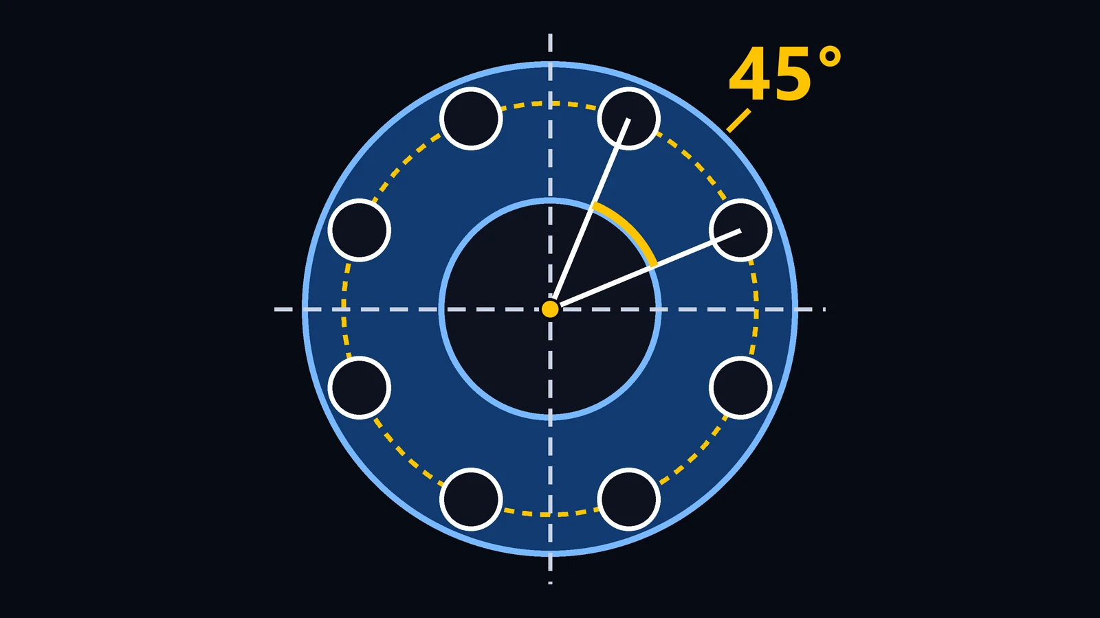
Flange bolt hole layout is one of the most common marking jobs in fabrication and piping work: bolt holes evenly spaced around a circle, which have to line up with the holes of the mating flange. When a flange is made in the shop, or the holes have to be marked from a drawing, the bolt circle calculation is what makes the bolts go in.
In this article we will work with the case of a round pipe flange:
N bolt holes (in the example, 8) evenly spaced around a bolt circle of diameter D, the circle that passes through the centers of the holes;
N a multiple of 4, as in ASME B16.5 flanges (4, 8, 12, 16...);
no hole on the vertical or horizontal centerline: the holes straddle them, one on each side;
dimensions in millimeters, with dividers, a rule and a center punch.
What the bolt circle is and what the standard asks for
The bolt circle is the circle through the center of every hole, not through the edge of the holes or the edge of the flange. Its diameter (D), the number of holes (N) and the diameter of each hole come from the flange table; in catalogs it is often just “bolt circle” (also called pitch circle diameter, PCD), and some tables label it K, next to the number of bolts.
For ASME B16.5 flanges, the rule for the bolt holes asks for three things: a number of holes that is a multiple of four, holes equally spaced, and holes in pairs that straddle the centerlines. With N a multiple of 4, the drilling is the same in all four positions in which the flange can be turned by 90°.
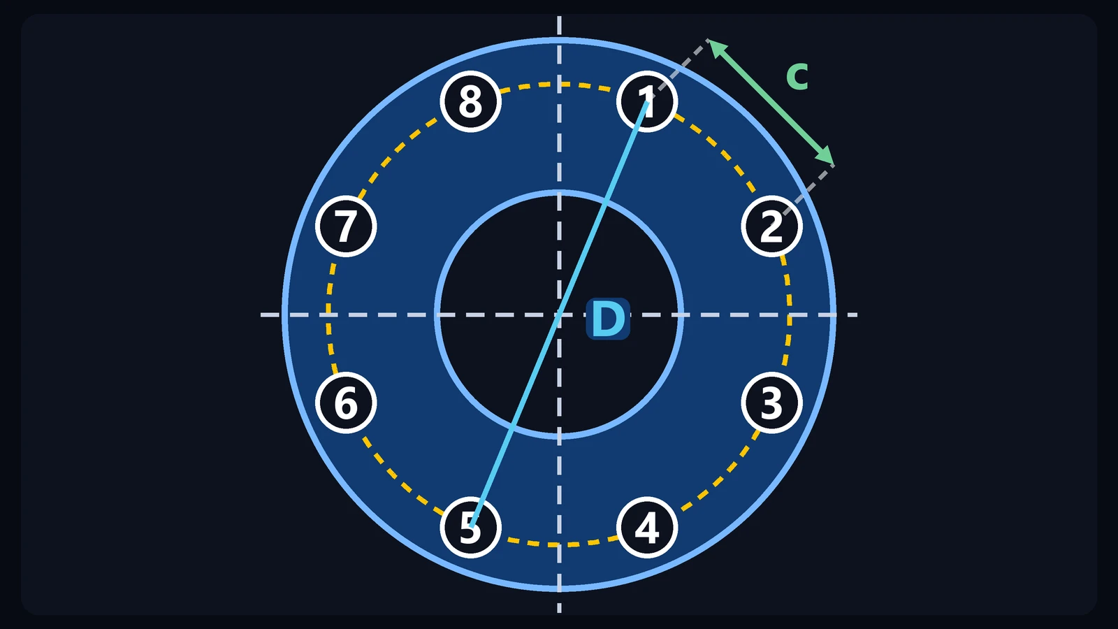
Figure 1: The flange in the example, with 8 holes numbered 1 to 8. The bolt circle (yellow, dashed) has diameter D, the blue line, measured between the centers of two opposite holes (1 and 5); c is the chord between two neighboring holes (1 and 2). The holes are enlarged in the drawing.
Flange bolt hole layout: angle, chord and hole position
The N holes divide the circle into N equal parts. The angle between two neighboring holes, the angular pitch, is 360° ÷ N.
To mark with dividers, what matters is the chord: the straight-line distance between the centers of two neighboring holes. It is c = D × sin(180° ÷ N), because the chord and the two radii form an isosceles triangle, and half of that triangle is a right triangle with an angle of 180° ÷ N at the center.
Since no hole falls on the centerline, the first hole sits half an angular pitch, 180° ÷ N, from the vertical centerline. So the two holes at the top are symmetric about it, and the distance between them is the chord c itself.
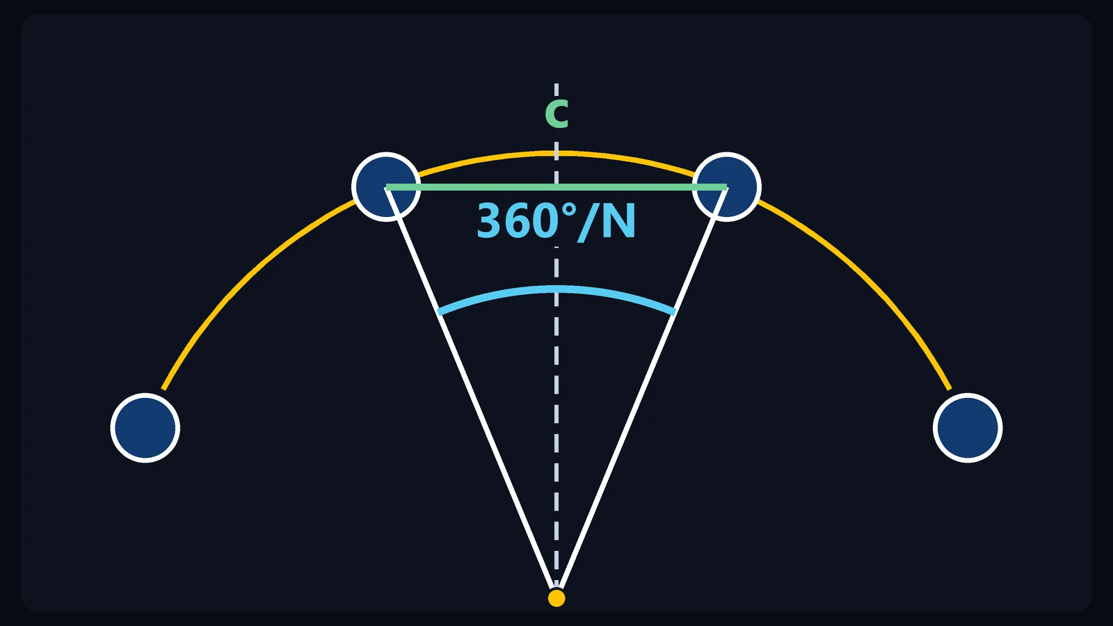
Figure 2: The top of the flange: the two holes next to the vertical centerline (dashed) sit one on each side of it, symmetric, and are c apart. The angle between them, seen from the center, is 360° ÷ N, with N the number of holes. The holes are enlarged in the drawing.
Example: NPS 4 flange, Class 150 (ASME B16.5)
Data from the table: bolt circle D = 190.5 mm and N = 8 holes of 19 mm.
angular pitch: 360 ÷ 8 = 45°; the first hole sits 22.5° from the vertical centerline;
factor: sin 22.5° = 0.38268;
chord: 190.5 × 0.38268 = 72.90 mm between neighboring holes;
radius: 190.5 ÷ 2 = 95.25 mm;
metal between two neighboring holes: 72.90 − 19 = 53.90 mm.
Carry TraceClub in your pocket
Boilermaking layouts, calculations and technical manuals in the palm of your hand — fast, accurate and always with you in the shop or in the field.
- Available for iOS and Android
- Works offline
- PT · EN · ES

Coordinates of each hole
To drill by coordinates (marking out, plasma cutting, CNC) or to check the marking, calculate the position of each hole from the center of the flange. With the angle θ measured from the vertical centerline, clockwise, x = R × sin θ (to the right) and y = R × cos θ (up). In the example, R = 95.25 mm:
Hole | θ (degrees) | x (mm) | y (mm) |
|---|---|---|---|
1 | 22.5 | +36.45 | +88.00 |
2 | 67.5 | +88.00 | +36.45 |
3 | 112.5 | +88.00 | −36.45 |
4 | 157.5 | +36.45 | −88.00 |
5 | 202.5 | −36.45 | −88.00 |
6 | 247.5 | −88.00 | −36.45 |
7 | 292.5 | −88.00 | +36.45 |
8 | 337.5 | −36.45 | +88.00 |
Check: holes 1 and 8 sit 36.45 mm on each side of the vertical centerline, and 2 × 36.45 = 72.90 mm is the chord. The table is symmetric about both centerlines, and every hole is 95.25 mm from the center.
Chord factor chart
Chord = D × factor, and the factor depends only on N. For D = 190.5 mm:
N (holes) | Angular pitch (degrees) | Factor sin(180° ÷ N) | Chord (mm) |
|---|---|---|---|
4 | 90 | 0.70711 | 134.70 |
8 | 45 | 0.38268 | 72.90 |
12 | 30 | 0.25882 | 49.31 |
16 | 22.5 | 0.19509 | 37.16 |
20 | 18 | 0.15643 | 29.80 |
Class 150 flange bolt holes: bolt circle and chord
Bolt circle, number of holes and hole diameter for Class 150, as they appear in flange manufacturers' tables, and the chord calculated with the formula above:
NPS | Bolt circle D (mm) | N | Hole (mm) | Chord c (mm) |
|---|---|---|---|---|
2" | 120.7 | 4 | 19 | 85.35 |
4" | 190.5 | 8 | 19 | 72.90 |
6" | 241.3 | 8 | 22 | 92.34 |
8" | 298.5 | 8 | 22 | 114.23 |
10" | 362.0 | 12 | 25.4 | 93.69 |
12" | 431.8 | 12 | 25.4 | 111.76 |
Confirm the values for your flange in the project table or in the standard: the bolt circle changes with the pressure class and with the standard (ASME B16.5, EN 1092-1).
Step by step: flange bolt hole layout
Confirm in the flange table the bolt circle D, the number of holes N and the hole diameter.
Calculate the factor sin(180° ÷ N) to 5 decimal places and the chord c = D × factor.
Draw the two perpendicular centerlines and mark the center of the flange.
With the dividers set to the radius R = D ÷ 2, draw the bolt circle.
Draw two lines parallel to the vertical centerline, one on each side, at a distance of c ÷ 2 from it. They cut the circle at the two top holes (holes 8 and 1 in Figure 1) and, mirrored, at the two bottom ones.
Set the dividers to the chord c and, starting from hole 1, mark the remaining holes around the circle.
Check the closing: from hole 1 to hole 8 there are 7 settings, and the last one has to land exactly on hole 8. If it falls short or long, adjust the setting a little and mark again; do not split the difference by eye.
Check the opposite holes: with N even, the distance between two opposite holes equals D.
Mark each center with the center punch and only then drill. ASME B16.5-2003 allows ±0.8 mm center to center of neighboring holes and ±1.5 mm on the bolt circle diameter.
Common mistakes in flange bolt hole layout
1. A hole on the centerline
This happens when marking without the calculation. With 8 holes, the first one lands on the vertical centerline, 95.25 mm from the center, and the drilling no longer matches factory flanges, whose holes sit 22.5° from the centerline.
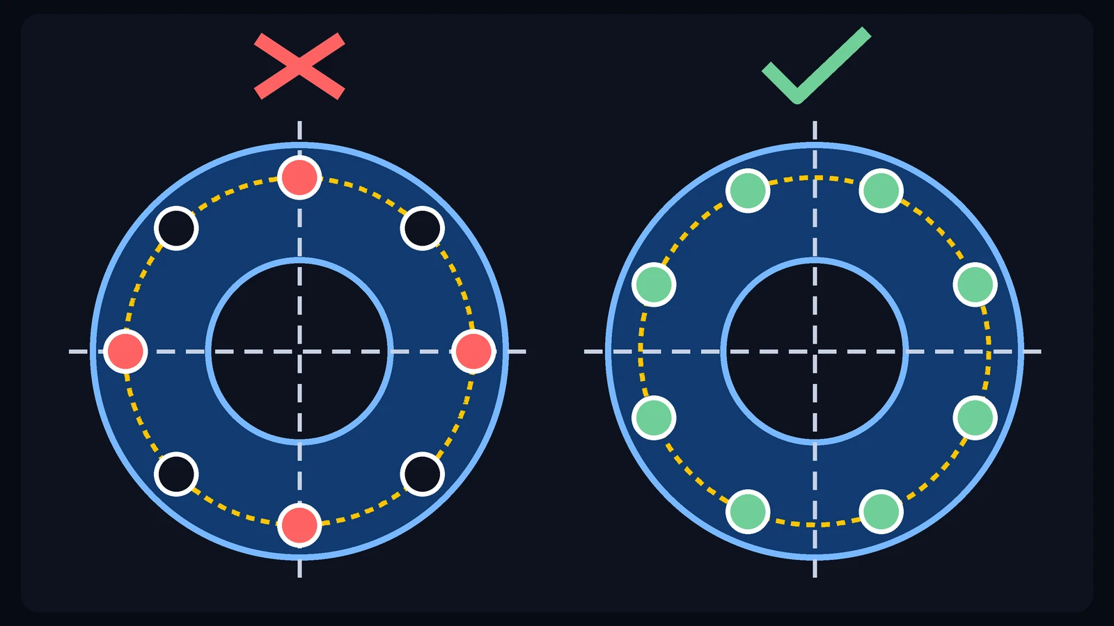
Figure 3: On the left, 8 holes with four of them on the centerlines, two on the vertical and two on the horizontal (in red): wrong. On the right, the first hole 22.5° from the vertical centerline and no hole on the centerlines (in green, all of them): right. The holes are enlarged.
2. Using the flange outside diameter instead of the bolt circle
The outside diameter of the NPS 4 flange in the table is 228.6 mm. In the formula the chord would come out as 228.6 × 0.38268 = 87.48 mm instead of 72.90 mm: 87.48 − 72.90 = 14.58 mm too much between holes.
3. Marking the arc instead of the chord
The arc between two centers measures 74.81 mm (3.1416 × 190.5 ÷ 8), longer than the chord. 74.81 − 72.90 = 1.91 mm too much per step.
4. Swapping 180° for 360° in the formula
With sin(360° ÷ 8) = sin 45° = 0.70711, the chord would come out as 190.5 × 0.70711 = 134.70 mm, which is the chord of a 4-hole flange.
5. Letting the divider error build up
An error of 0.3 mm in the setting adds up to 7 × 0.3 = 2.1 mm of extra chord by hole 8 and, in practice, hole 8 ends up about 2.3 mm off position. That is why the last step has to land on hole 8 before drilling.
Flange bolt hole layout: questions and answers
How many bolt holes does a flange have?
It depends on the size and the class. In Class 150, NPS 2 has 4 holes, NPS 4 to NPS 8 have 8 holes and NPS 10 and 12 have 12. ASME B16.5 asks for a number of holes that is a multiple of four.
How do you calculate the chord of a 6-hole flange?
With N = 6, sin 30° = 0.5 and the chord equals the radius: 190.5 × 0.5 = 95.25 mm. Six holes do not follow the ASME B16.5 rule (multiple of four), but they show up on custom-designed flanges, blind flanges and cover plates; in that case the position relative to the centerlines is the one on the drawing.
How do you lay out a 12-hole flange?
For NPS 10 in Class 150, D = 362 mm and N = 12: the angular pitch is 30°, the first hole sits 15° from the vertical centerline and the chord is 362 × 0.25882 = 93.69 mm.
Does the calculation work for EN 1092-1?
The method is the same; only the table values change. For PN 16, DN 100, the bolt circle is 180 mm, with 8 holes of 18 mm: the chord is 180 × 0.38268 = 68.88 mm. Check the position of the first hole on the drawing.
How do you calculate the metal between two holes?
It is the chord minus the hole diameter: 72.90 − 19 = 53.90 mm in the example. If the result is negative, the holes overlap. For the weight of the drilled flange or plate, see Steel Plate Weight Calculation: Plate and Pipe, With Charts.
See also
Summary
Flange bolt hole layout: angular pitch of 360° ÷ N, chord c = D × sin(180° ÷ N), first hole at 180° ÷ N from the centerline and opposite holes a distance D apart.
Important
The table values in this article are for ASME B16.5 Class 150 flanges and from manufacturers' catalog examples. Always confirm the bolt circle, the number of holes and the hole diameter in the table or on the drawing of your project before marking. Clamp the part and wear personal protective equipment (PPE) when drilling and cutting. The article does not replace the standard or the assembly procedure of your workplace.
Carry TraceClub in your pocket
Boilermaking layouts, calculations and technical manuals in the palm of your hand — fast, accurate and always with you in the shop or in the field.
- Available for iOS and Android
- Works offline
- PT · EN · ES