
Off-Center Fishmouth Layout: 90° Branch With Offset Axes
An off-center fishmouth, with the branch axis offset from the main pipe: depth formula with the offset, parallel-line development and a measurement table.
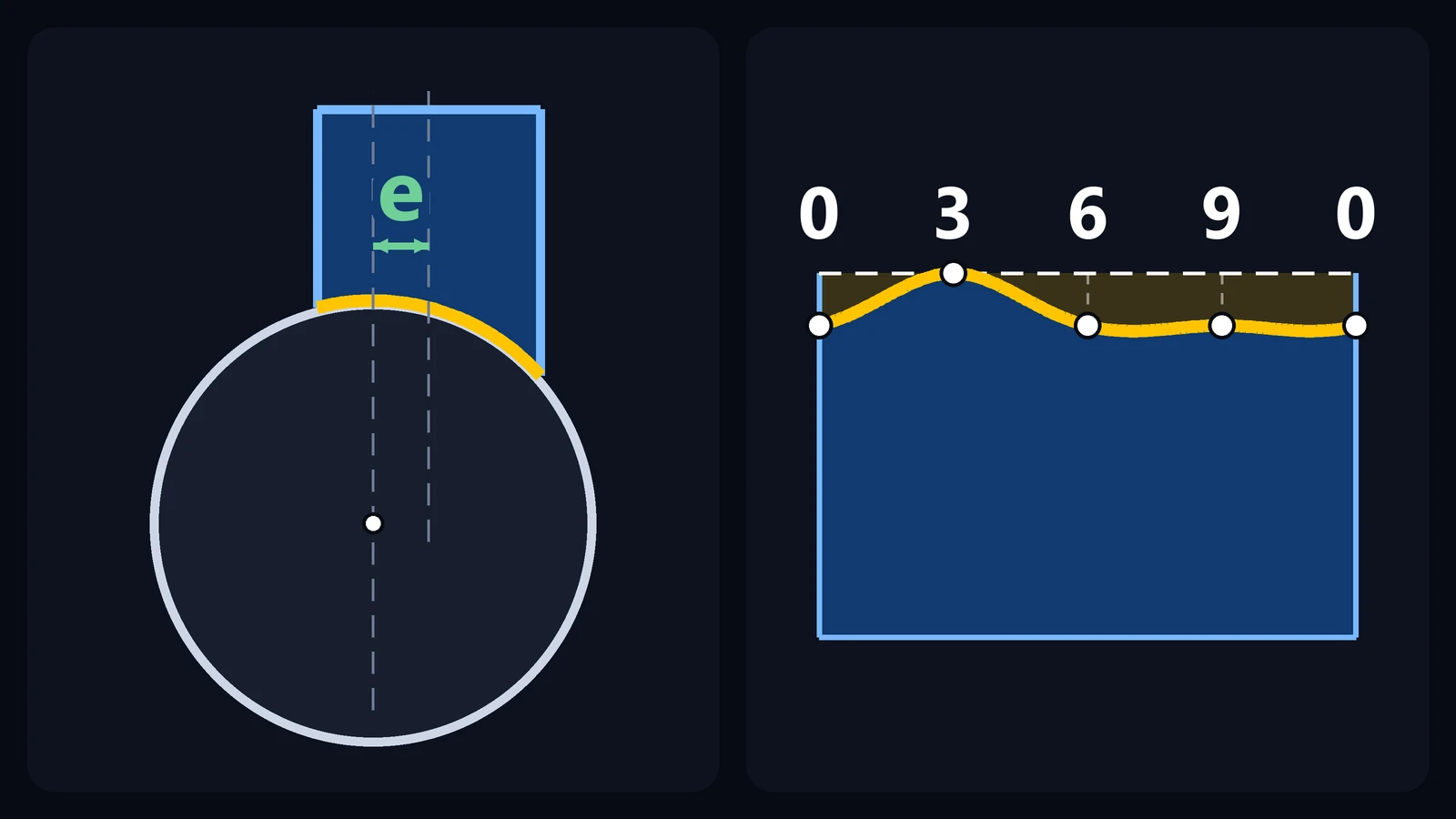
An off-center fishmouth is the fishmouth cut on a branch whose axis does not intersect the axis of the main pipe: the two axes are at 90° to each other but are offset by a distance e (the eccentricity) and never meet. Pattern-development books call the joint an off-center tee or an eccentric branch. When the axes do intersect, the layout is the one in the fishmouth joint between pipes of different diameters; here the cut changes because its two sides are no longer equal.
Do not confuse it with an eccentric reducer, a transition piece between two diameters whose axes are also offset (see how to lay out an eccentric reducer): its pattern is different and is not covered here.
In this article we work with one specific situation:
a branch smaller than the main pipe and lying entirely within its outline (e ≤ R − r);
axes at 90° and offset from each other by a distance e, with no intersection;
the pattern for the end of the branch, the pipe that will be fitted.
Another angle, a branch that leaves through the side of the main pipe (e > R − r) and the opening in the main pipe, where the branch will be welded, require a different layout and are not covered here.
What changes in an off-center fishmouth
Let R be the radius of the main pipe and r the radius of the branch. The distance between the two axes is the offset e, with e ≤ R − r. Each element line of the branch, that is, each straight line on its surface parallel to its axis, lies at a distance z from the axis of the main pipe, measured in the end view:
z = e + r × sin θ
Here, θ is the position of the element line on the branch circle: point 0 (θ = 0°) lies on the line parallel to the main pipe's axis that passes through the center of the branch, point 3 (θ = 90°) is on the side farthest from the main pipe's axis and point 9 (θ = 270°) is on the opposite side. The height at which the element line meets the main pipe is y = √(R² − z²).
When the axes intersect (e = 0), points 3 and 9 are at the same distance from the main pipe's axis, and the side of point 3 and the side of point 9 of the cut are equal, mirror images of each other: calculating one of them and copying it onto the other would be enough. With the axis offset, that ends: the branch runs closer to one side of the main pipe than to the other, and the two sides differ. The side of point 3, toward which the branch is offset, ends up touching the baseline (zero depth); the side of point 9 does not. That is why the whole circumference has to be divided and the depths of both sides calculated, without copying one onto the other.
The element line at point 3, where z is as large as it gets (z = e + r), is the one that meets the main pipe lowest, at the smallest height y: in the finished piece, it is the longest, and nothing is cut off it. The square-cut end of the branch touches it, at a height y₀ = √(R² − (e + r)²), and the depth on each element line, measured from that end, is:
h = √(R² − (e + r × sin θ)²) − √(R² − (e + r)²)
Two limiting cases help as a check. With e = 0, the formula goes back to the one for different diameters, h = √(R² − r² × sin²θ) − √(R² − r²). With e = R − r, the side of the branch touches the side of the main pipe (y₀ = 0), and the depth of each element line is its own height y.
As long as e ≤ r, some element lines have z = 0, passing through the plane of the main pipe's axis. They are the deepest, that is, the shortest in the finished piece, and the maximum depth is h = R − √(R² − (e + r)²).
Measurements you need
Measurement | Meaning |
|---|---|
D and R | Outside diameter of the main pipe and its radius, R = D ÷ 2 |
d and r | Outside diameter of the branch and its radius, r = d ÷ 2 (smaller than R) |
e | Offset (eccentricity): distance between the axis of the branch and the axis of the main pipe, measured in the end view (e ≤ R − r) |
n | Number of divisions of the branch circumference (here, 12) |
L | Length of the branch, measured along its axis, from the square-cut end to the free end |
In the example, the main pipe has D = 200 mm (R = 100 mm), the branch has d = 100 mm (r = 50 mm) and the offset is e = 25 mm. The limit is R − r = 50 mm, and the offset of 25 mm is within it.
If the drawing gives the distance from the axis of the main pipe to the farthest side of the branch, that dimension is e + r (75 mm in the example): subtract r to get e.
Step-by-step off-center fishmouth layout (parallel-line development)
Step 1 — Draw the views
Draw two views, one above the other, with the horizontal distances lined up. At the bottom, the end view of the main pipe: the circle of radius R (the upper half is enough), centered on the axis of the main pipe. Above it, the top view of the branch: the axis of the main pipe shows up as a vertical line, and the circle of the branch, of radius r, is centered on another vertical line, a distance e from the first.
Step 2 — Divide the branch circumference
Divide the circle in the top view into 12 equal parts of 30° and number the points from 0 to 11, clockwise. Point 0 lies on the line parallel to the main pipe's axis that passes through the center of the branch, and point 3 is on the side farthest from that axis, that is, the side toward which the branch is offset. Note this down: point 3 is the reference for the whole job. Point 9, on the opposite side, is closer to the axis of the main pipe.
Step 3 — Transfer each distance to the end view
Each point in the top view marks an element line of the branch: the divisions of the circle are projected by lines parallel to the branch axis. Measure the distance z from each point to the line of the main pipe's axis (z = e + r × sin θ; in the example, for the points on the other side of that line, 8, 9 and 10, z is negative). In the end view, draw a vertical line at that same distance z from the center (on the other side of the center if z is negative). The point where it meets the circle of radius R, on the upper side, gives the height y of the intersection.
Step 4 — Set the baseline and measure the depths
The vertical through point 3, the one farthest from the main pipe's axis (z = e + r = 75 mm), meets the circle at a height y₀ = √(R² − (e + r)²) = √(10,000 − 5,625) = √4,375 = 66.14 mm. This is the baseline: it coincides with the square-cut end of the branch. The depth of each point is the difference between its height y and the baseline. Here only point 3 touches the baseline; with intersecting axes, both sides (points 3 and 9) touched it.
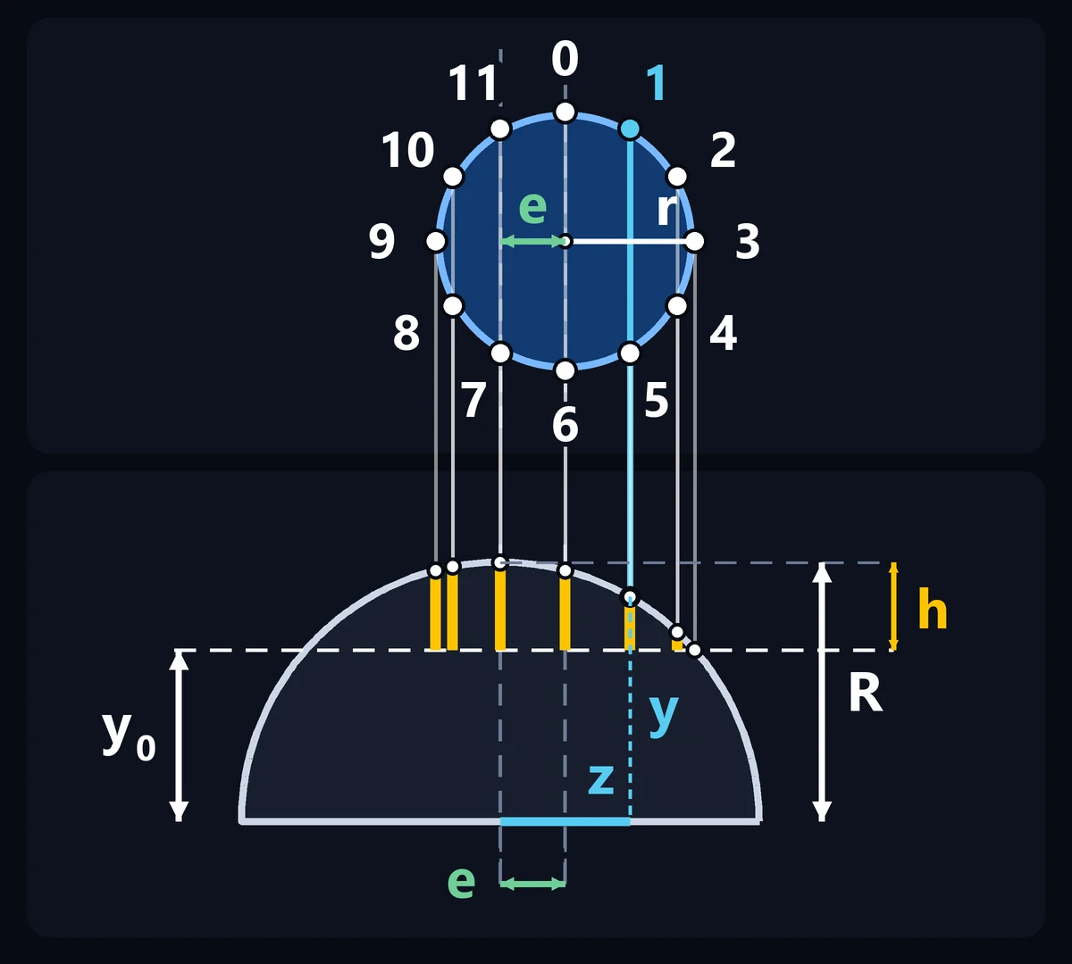
Figure 1: Construction drawn to scale (the same scale in both views). Top: the top view of the branch (radius r) with its 12 points; the axis of the main pipe is the dashed vertical line on the left and the axis of the branch is the one on the right, a distance e away. Bottom: the upper half of the end view of the main pipe (radius R). The vertical line from each point, at a distance z from the axis of the main pipe, meets the circle at height y, and the depth h is the difference from the baseline y₀ (the height of point 3). Point 1 is highlighted.
Step 5 — Check with the formula
For point 1 (θ = 30°), z = 25 + 50 × 0.5 = 50 mm. Then y = √(10,000 − 2,500) = √7,500 = 86.60 mm and the depth is 86.60 − 66.14 = 20.46 mm.
For point 7 (θ = 210°), sin 210° = −0.5 and z = 25 − 25 = 0: the element line passes through the plane of the main pipe's axis and y = R = 100 mm. The depth is 100 − 66.14 = 33.86 mm, the maximum. Point 11 gives the same value, because it also has z = 0.
For point 9 (θ = 270°), z = 25 − 50 = −25 mm: on the other side of the axis, the vertical line is 25 mm from the center. Then y = √(10,000 − 625) = √9,375 = 96.82 mm and the depth is 96.82 − 66.14 = 30.68 mm.
Step 6 — Calculate the stretch-out
The branch circumference is C = π × d. With π = 3.1416 and d = 100 mm, C = 314.16 mm. Divided into 12 parts, each division measures 314.16 ÷ 12 = 26.18 mm.
On paper or cardboard, draw a straight line 314.16 mm long (the stretch-out line), mark the 12 divisions and number them 0 to 11 (point 12 is the same as point 0).
Step 7 — Transfer the depths
Erect a perpendicular at each division. Starting from the stretch-out line, which represents the square-cut end of the branch, measure each point's depth inward, toward the free end, using the table below. Only point 3 sits on the line.
Step 8 — Join the points
Join the points with a smooth, continuous curve, with no sharp tips. It is symmetrical about points 3 and 9, but the two sides are different: around point 3 the curve rises to the line, and around point 9 it stays away from it (30.68 mm). That is why you cannot copy one side onto the other.
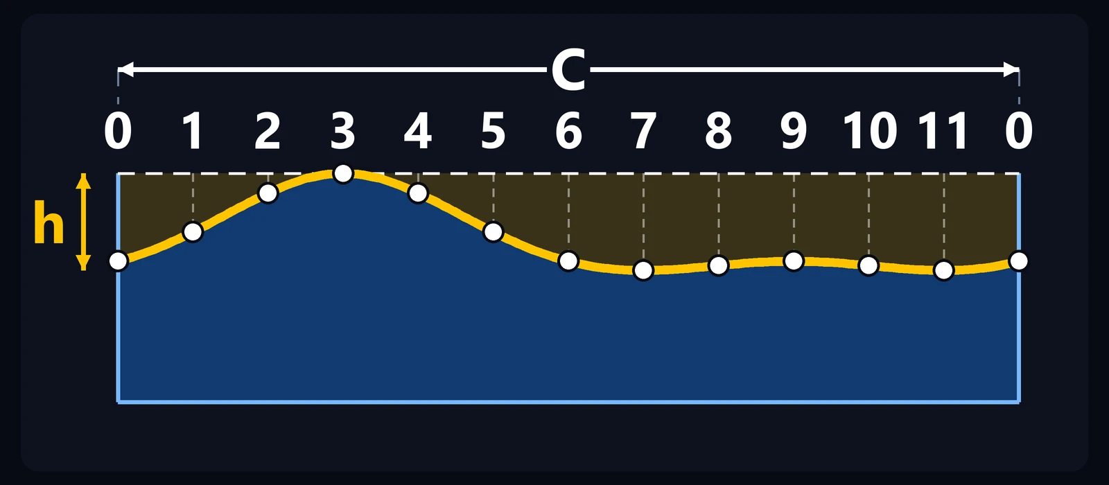
Figure 2: The template laid out flat, drawn to the same scale in both directions, with the stretch-out C = π × d divided into 12 parts. The dashed line is the square-cut end; the yellow curve runs through the 12 points, and the area between the line and the curve is what gets cut away. Only point 3 touches the line; the curve is symmetrical about points 3 and 9, but the two sides are different. The height of the strip below the curve is only illustrative.
Step 9 — Cut square, make the template, orient it and check it
Cut the branch square to length L, measured along the axis from the square-cut end. If the drawing gives the dimension from the main pipe's axis, subtract the baseline: L = dimension − 66.14 mm. Length L must be greater than the maximum depth (33.86 mm in the example); for that, a dimension greater than R (100 mm in the example) is enough. Then cut out the template. Mark on the pipe the element line of point 3 (a straight line along the pipe); at assembly, it lies on the side toward which the branch is offset. Wrap the template around the pipe, with its base on the square-cut end and point 3 on that element line. Mark the outline and check that point 3 sits at the end and that point 9 falls on the other side of the pipe. Only then cut along the profile. After cutting, check the fit on the main pipe and adjust with a file or grinder if needed.
Carry TraceClub in your pocket
Boilermaking layouts, calculations and technical manuals in the palm of your hand — fast, accurate and always with you in the shop or in the field.
- Available for iOS and Android
- Works offline
- PT · EN · ES
Measurement table: 100 mm branch on a 200 mm pipe, with e = 25 mm
Values for D = 200 mm, d = 100 mm, e = 25 mm, axes at 90° and 12 divisions. Depth is measured from the square-cut end of the branch. The distance z is measured from the axis of the main pipe; a negative sign means the other side of that axis.
Point | z (mm) | Position on the stretch-out (mm) | Depth (mm) | Note |
|---|---|---|---|---|
0 | 25.00 | 0.00 | 30.68 | |
1 | 50.00 | 26.18 | 20.46 | |
2 | 68.30 | 52.36 | 6.90 | |
3 | 75.00 | 78.54 | 0.00 | zero depth: touches the baseline |
4 | 68.30 | 104.72 | 6.90 | |
5 | 50.00 | 130.90 | 20.46 | |
6 | 25.00 | 157.08 | 30.68 | |
7 | 0.00 | 183.26 | 33.86 | deepest point (z = 0) |
8 | −18.30 | 209.44 | 32.17 | |
9 | −25.00 | 235.62 | 30.68 | negative z: other side of the axis |
10 | −18.30 | 261.80 | 32.17 | |
11 | 0.00 | 287.98 | 33.86 | deepest point (z = 0) |
The maximum depth is 33.86 mm (points 7 and 11). For comparison: with intersecting axes (e = 0), it would be 13.40 mm. The values repeat in pairs (0 and 6, 1 and 5, 2 and 4, 7 and 11, 8 and 10) because the curve is symmetrical about points 3 and 9; point 9 also matches 0 and 6 only because, in this example, e = r ÷ 2. If your layout gives different values, check it before cutting.
How the offset changes the depth
With the same pair of pipes (D = 200 mm and d = 100 mm), the maximum depth grows quickly as the branch moves away from the center:
e (mm) | e + r (mm) | Maximum depth (mm) |
|---|---|---|
0 | 50 | 13.40 |
15 | 65 | 24.01 |
25 | 75 | 33.86 |
40 | 90 | 56.41 |
50 | 100 | 100.00 |
Each value comes from R − √(R² − (e + r)²), which holds while e ≤ r (here, r = 50 mm). In the last row, e = R − r: the side of the branch touches the side of the main pipe, y₀ = 0 and the maximum depth reaches R (100 mm), the limit of the formula.
These values are the maximum of the continuous curve. With 12 divisions, the largest value that shows up at the points can be a little lower: with e = 15 mm, for example, it is 23.51 mm (points 7 and 11), and with e = 40 mm, 56.36 mm (points 8 and 10).
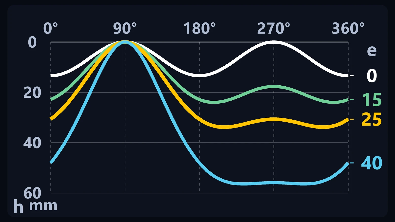
Figure 3: Depth h of the cut along the circumference (0° to 360°), with the actual values, for e = 0, 15, 25 and 40 mm, with a 200 mm main pipe and a 100 mm branch. With e = 0 the two halves are equal; the larger e is, the deeper and less symmetrical the cut. The zero depth at 90° (point 3) exists on every curve; the one at 270° (point 9) only reaches zero when e = 0.
The chart shows the whole curve, from 0° to 360°. The zero depth at 90° (point 3) exists on every curve; the one at 270° (point 9) only reaches zero when e = 0.
What if the part is made from plate?
When the pipes are rolled from plate, use the mean diameter of each one, that is, the outside diameter minus the wall thickness. Example with a 200 mm main pipe with 6 mm wall thickness, a 100 mm branch with 5 mm wall thickness, and e = 25 mm between the axes:
main pipe: 200 − 6 = 194 mm, or R = 97 mm;
branch: 100 − 5 = 95 mm, or r = 47.5 mm;
baseline: y₀ = √(97² − (25 + 47.5)²) = √(9,409 − 5,256.25) = √4,152.75 = 64.44 mm;
C = 3.1416 × 95 = 298.45 mm, or 24.87 mm per division;
maximum depth: 97 − 64.44 = 32.56 mm (that of the continuous curve; at the 12 points, the largest value is 32.55 mm).
The offset (e) is still the distance between the axes of the two pipes. This is a common approximation: the weld bevel and the final gap should be adjusted at fit-up.
Common mistakes when laying out an off-center fishmouth
1. Using the layout for intersecting axes
For a 100 mm branch on a 200 mm pipe, that layout gives a maximum depth of 13.40 mm. With e = 25 mm, the correct depth is 33.86 mm, and the part will not fit.
2. Copying one side of the pattern onto the other
The shortcut of calculating one side and copying it onto the other only holds when the axes intersect. With e ≠ 0, the side of point 3 and the side of point 9 are different: divide and calculate the whole circumference.
3. Putting point 3 on the wrong side
Point 3, the one with zero depth, must be on the side toward which the branch is offset. With the template turned 180°, the cut comes out swapped and the part will not fit.
4. Mixing up the side dimension with the offset
The offset (e) is the distance between the axes. The distance from the main pipe's axis to the farthest side of the branch is e + r (75 mm in the example, not 25 mm).
5. Going past the limit e ≤ R − r
If e > R − r, the branch leaves through the side of the main pipe: some element lines pass beside it and never touch it, the calculation of the height y asks for the square root of a negative number, and the layout is different.
6. Using the nominal diameter
The layout depends on the actual outside diameter of both pipes. Measure the pipes; do not rely on the nominal diameter alone.
7. Measuring depth from another reference
All depths come from the same baseline, the square-cut end. Mixing references shifts the whole cut.
Frequently asked questions
What is an off-center fishmouth?
It is the fishmouth cut on a branch whose axis passes offset from the axis of the main pipe, without intersecting it. The axes are at 90°, and the distance between them is the offset (e), also called the eccentricity. The two sides of the cut are no longer equal, and the whole circumference has to be developed.
What is the difference from a fishmouth with intersecting axes?
With intersecting axes (e = 0), the two sides of the curve are equal and, in the example, the maximum depth is 13.40 mm. With the axis offset, the two sides are no longer mirror images of each other and the maximum depth goes up (33.86 mm with e = 25 mm). For the e = 0 case, see the article on the fishmouth between pipes of different diameters.
How deep is an off-center fishmouth cut?
Use h = √(R² − (e + r × sin θ)²) − √(R² − (e + r)²), where θ is the position of each element line and the depth is measured from the square-cut end. In the example (200 mm main pipe, 100 mm branch and e = 25 mm), the maximum depth is 33.86 mm.
How far can the branch be offset in this layout?
Up to e = R − r: at that limit, the side of the branch touches the side of the main pipe. In the example, R − r = 50 mm. Beyond that, the layout is different and is not covered here.
Can I use this layout for 45° or another angle?
No. This article covers axes at 90°. For a 45° branch with intersecting axes, see the 45 degree lateral layout article.
Can I use a different number of divisions?
Yes. The number must be a multiple of 4 (12, 16, 24), so that the positions at 90° and 270° (points n ÷ 4 and 3n ÷ 4; with 12 divisions, 3 and 9) fall exactly on a division. More divisions give you more points to join.
See also
Fishmouth Joint Layout for Different Pipe Diameters: 90° Branch
Eccentric cone in metal fabrication: difference between concentric and eccentric reducers
Step-by-step summary
To lay out an off-center fishmouth at 90°:
draw the end view of the main pipe and, lined up with it, the top view of the branch, with its axis offset by e;
divide the branch circumference into 12 parts and number them 0 to 11, with point 3 on the side toward which it is offset;
for each point, calculate z = e + r × sin θ and find the height y = √(R² − z²) on the circle of radius R;
take the height of point 3, y₀ = √(R² − (e + r)²), as the baseline and measure each depth from it;
calculate the stretch-out C = π × d and divide it into the same number of parts;
transfer the depths from the square-cut end, without copying one side onto the other;
join the points with a smooth curve;
cut square, make the template, orient point 3, check the marked outline, cut, and only then check the fit.
Important
This article covers specifically the case of a branch smaller than the main pipe, with axes at 90° offset by a distance e (e ≤ R − r). Changing any of these conditions changes the pattern. When cutting the pipe, wear appropriate personal protective equipment and secure the workpiece firmly.
Carry TraceClub in your pocket
Boilermaking layouts, calculations and technical manuals in the palm of your hand — fast, accurate and always with you in the shop or in the field.
- Available for iOS and Android
- Works offline
- PT · EN · ES